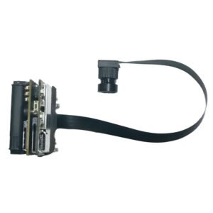
Category: MIPI camera module

MIPI vs DVP Camera Modules
MIPI camera module
Opti Bridge Solutions

MIPI vs DVP Camera Modules: A Practical Guide for STM32, ESP32, IoT, Drone and Wildlife Camera Projects

Pick up almost any modern embedded camera datasheet and you will meet two acronyms within the first page: DVP and MIPI. They describe how the image gets from the sensor to your processor, and choosing the wrong one is one of the most expensive mistakes in a camera project. It can mean a processor that physically cannot connect to the sensor, a board with far too many traces, or a video stream that stutters because the link is too slow. This guide explains the difference in plain terms, then walks through real module choices for microcontroller boards, IoT devices, doorbells, wildlife cameras and drones. It comes from the team at Shenzhen Brilliant CMOS Technology Co., Ltd., where we design and supply OEM and ODM camera modules, so it focuses on the decisions that actually cause problems in development. In this guide What a CMOS sensor does, and what the module adds DVP vs MIPI: the core difference Which interface does your processor support? OV5640: the versatile 5MP workhorse STM32 and microcontroller camera projects ESP32 camera and Arduino projects A compact 2MP option for IoT and cost-sensitive products IR-cut cameras for doorbells and day/night use Wildlife and bird watching cameras 4K modules for IoT, drones and advanced imaging Module comparison at a glance A practical selection checklist Frequently asked questions 1. What a CMOS sensor does, and what the module adds The cmos sensor is the chip that turns light into an electrical signal. Millions of tiny light-sensitive pixels each measure how much light reaches them, and the chip reads those values out as image data. CMOS sensors dominate modern cameras because they are low-power, fast and cheap to manufacture, and they can integrate image-processing functions on the same chip. But a bare sensor is not a camera. A camera module adds everything else you need to get a usable picture: A lens matched to the sensor, with the right field of view and focus type A focus mechanism, either fixed focus or an autofocus actuator An infrared filter (or an IR-cut arrangement) so colours look natural A flexible cable or connector to link the module to your board A tested, tuned assembly, so every unit behaves consistently Buying a module rather than a bare sensor saves months of optical design, alignment and tuning. That is exactly why embedded teams choose modules. 2. DVP vs MIPI: the core difference DVP (Digital Video Port) is a parallel interface. It sends pixel data across a bundle of separate wires at once (commonly 8 or 10 data lines), accompanied by a pixel clock and synchronisation signals for lines and frames. MIPI CSI-2 is a serial interface. It sends data as high-speed differential pairs called lanes, typically one, two or four, plus a clock pair. Fewer wires carry far more data. Here is what that means in practice:   DVP MIPI CSI-2 Signal type Parallel, single-ended Serial, differential lanes Typical pin count High (often 20 or more connections) Low (a few signal pairs) Bandwidth Modest High, scales with lanes Typical resolutions Up to a few megapixels, lower frame rates Multi-megapixel up to 4K and beyond Board design Easy to prototype, but many traces Needs careful controlled-impedance routing Processor support Common on microcontrollers Common on application processors and newer SoCs Cable length and noise Short runs preferred Better for longer runs and noise immunity The short version: DVP is simple and widely supported on small processors but limited in speed and wire-hungry. MIPI is the modern choice for high resolution and frame rate, but needs a processor with a MIPI CSI-2 receiver and more careful PCB design. 3. Which interface does your processor support? This is the question to answer first, because it decides everything else. A camera interface is a hardware block on the processor. If your chip does not have a MIPI receiver, no software can add one. Many microcontrollers provide a parallel camera interface, so DVP modules connect directly. Application processors and modern SoCs, such as those on single-board computers and smart devices, typically include MIPI CSI-2 receivers. Some processors have both, which gives you the freedom to choose by performance and cost. Always check the exact part number in the manufacturer’s reference manual: not just the family. Interface availability can differ between variants of the same product line. If your processor has only DVP but you need MIPI-class sensors, discuss bridge or alternative architectures with our team early. 4. OV5640: the versatile 5MP workhorse If you search for an OV5640 camera module, you are looking at one of the most widely used 5-megapixel sensors in embedded design. Its popularity comes from solid image quality for its class, broad software support, autofocus options on many modules and a long history in products. Our 5MP OV5640 CMOS sensor DVP camera module with a 24-pin interface is a straightforward choice for projects with a parallel camera port. It also serves as a compact camera module for products where space and board area are limited, while still giving a clear step up from VGA and 2MP options. If your design needs both interface options or an IR-cut filter, see our 5MP fixed-focus OV5640 / OV5648 OEM MIPI/DVP IR-cut camera module, which is offered for OEM customisation across interface styles. What to check on any OV5640-based module Frame rate at full resolution. Full 5MP frame rates on a parallel interface are lower than at reduced resolutions, so confirm the mode you need. Focus type. Fixed focus is robust and cheap; autofocus helps when subject distance varies. Connector pinout. Confirm the 24-pin pin order against your board to avoid a costly layout error. Clock and power requirements. The sensor needs an input clock and several supply voltages, so review them against your power design. 5. STM32 and microcontroller camera projects Searching for an STM32 MIPI camera usually means one of two things: someone using an STM32 microcontroller with a camera port, or someone choosing a sensor for a newer STM32 part that supports a serial camera interface.
Read More »
MIPI Camera Modules Explained: The Complete OEM Guide for Embedded Vision, AI and Industrial Applications
MIPI camera module
Opti Bridge Solutions

MIPI Camera Modules Explained: The Complete OEM Guide for Embedded Vision, AI and Industrial Applications

When an OEM begins developing an embedded vision product, the camera interface becomes an architectural decision rather than a simple component choice. It affects PCB layout, processor selection, power consumption, image latency, software development, thermal behavior and the space available inside the enclosure. A sensor with excellent laboratory performance can still become the wrong choice if its interface does not match the host platform or if the image pipeline cannot be supported in production. For compact systems that connect the image sensor directly to an application processor, a MIPI camera module is often the most efficient option. MIPI CSI-2 transfers image data over high-speed differential lanes, allowing high-resolution video to move from the sensor to the processor with low overhead and a small physical footprint. This architecture is common in smartphones, but it is equally relevant to robotics, edge AI devices, medical instruments, smart access products, drones and industrial embedded systems. MIPI is not automatically better than USB or DVP. It usually requires closer coordination between the camera module, processor, device tree, driver, image signal processor and PCB design. The engineering advantage appears when those elements are planned together. This guide explains how OEM teams can evaluate MIPI camera modules, identify integration risks early and build a specification that supports both prototype performance and long-term production. Contents What is a MIPI camera module? Why OEM teams choose MIPI CSI-2 How the camera-to-processor pipeline works MIPI versus USB and DVP Core specifications to evaluate Common embedded vision applications Building an OEM camera specification Prototyping, validation and production Frequently asked questions What Is a MIPI Camera Module? A MIPI camera module is a board-level imaging assembly that sends image data to a host processor through the MIPI Camera Serial Interface, most commonly CSI-2. A typical module combines a CMOS image sensor, lens, printed circuit board, clock and power components, control lines and a compact board-to-board or flexible-cable connector. Unlike a USB camera, it normally does not present itself as a complete peripheral. The host processor must support the sensor, receive the CSI-2 stream and process the raw or preprocessed image data. This tighter integration is one reason MIPI modules can be compact and power-efficient. It is also why compatibility cannot be assumed from the connector alone. Two modules may use similar physical connectors while differing in lane count, voltage levels, clocking, pin assignment, sensor initialization, Bayer pattern, data format or driver requirements. A successful design therefore begins with the processor platform and supported camera pipeline, not only with the desired megapixel rating. CBRITECH organizes these products within its MIPI Camera Module collection, where engineers can compare sensor, resolution and optical configurations for embedded projects. Related board-level options are also available in the broader CMOS Sensor Camera Module range. Why OEM Teams Choose MIPI CSI-2 Compact integration: The sensor can sit close to the processor or connect through a short flexible cable, helping product designers reduce enclosure volume. High data throughput: Multiple differential lanes support high-resolution and high-frame-rate image streams without the overhead of a general-purpose external bus. Low latency: Direct transfer into the processor image pipeline is valuable for robotics, visual feedback and real-time inference. Power efficiency: MIPI is designed for embedded and mobile electronics where energy consumption and heat generation must be controlled. Access to the processor ISP: The system can use the host image signal processor for demosaicing, exposure, white balance, noise reduction and color tuning. Flexible product architecture: The same processor platform may support different sensors if drivers, lane configurations and ISP tuning are properly managed. These advantages come with additional engineering responsibility. A UVC-compatible USB module can often be tested quickly on a PC, while a MIPI design may require a sensor driver, device-tree configuration, clock settings, regulator sequencing and ISP calibration before the first usable image appears. MIPI is therefore most attractive when the product needs compact integration and controlled performance, and the development team can manage the camera pipeline. How the Camera-to-Processor Pipeline Works The lens focuses light onto the CMOS sensor, where each pixel converts light into an electrical signal. The sensor reads the pixel array, applies its internal timing and gain controls, and transmits image data through one or more CSI-2 lanes. A separate I2C or similar control interface is typically used to configure exposure, gain, frame timing and operating modes. At the host, the CSI receiver reconstructs the stream and forwards it to the processor’s image pipeline. If the sensor outputs raw Bayer data, the ISP may perform demosaicing, white balance, color correction, lens shading correction, noise reduction, gamma and sharpening. The processed frames can then be encoded, displayed or passed to an AI model. This division of responsibility matters when evaluating image quality. The sensor determines fundamental characteristics such as pixel size, quantum efficiency, read noise, dynamic range and shutter architecture. The lens determines field of view, distortion, aperture and focus. The ISP and tuning determine how the raw signal is converted into a usable image. Changing only one element may not solve a system-level problem. Understanding CSI-2 Lanes and Bandwidth MIPI CSI-2 commonly uses one, two or four data lanes together with a clock lane, depending on the sensor and host. More lanes can provide greater throughput, but the usable configuration must be supported by both sides. Resolution alone does not determine bandwidth. Frame rate, bit depth, blanking intervals, HDR modes and embedded metadata also contribute to the data rate. An engineer should confirm the exact output mode rather than assuming that a four-lane connector guarantees maximum performance. A sensor may support several combinations, such as four lanes at a lower per-lane rate or two lanes at a higher rate. The processor may impose its own lane-speed limits, virtual-channel restrictions or supported data types. MIPI Versus USB and DVP Camera Modules Selection Factor MIPI CSI-2 USB/UVC DVP/Parallel Best fit Compact embedded products PCs, industrial computers and fast prototypes Lower-resolution MCUs and simpler embedded designs Integration effort Higher; driver and platform support required Often lower with UVC Moderate; parallel pin count

Read More »

We will contact you within 1 working day, please pay attention to the email with the suffix “@cbritech.com”

One Request, Multiple Quotes