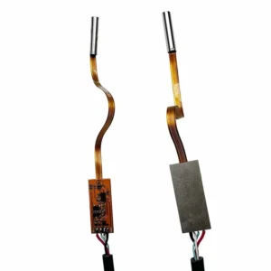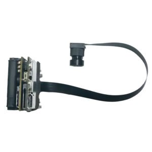

When an OEM begins developing an embedded vision product, the camera interface becomes an architectural decision rather than a simple component choice. It affects PCB layout, processor selection, power consumption, image latency, software development, thermal behavior and the space available inside the enclosure. A sensor with excellent laboratory performance can still become the wrong choice if its interface does not match the host platform or if the image pipeline cannot be supported in production.
For compact systems that connect the image sensor directly to an application processor, a MIPI camera module is often the most efficient option. MIPI CSI-2 transfers image data over high-speed differential lanes, allowing high-resolution video to move from the sensor to the processor with low overhead and a small physical footprint. This architecture is common in smartphones, but it is equally relevant to robotics, edge AI devices, medical instruments, smart access products, drones and industrial embedded systems.
MIPI is not automatically better than USB or DVP. It usually requires closer coordination between the camera module, processor, device tree, driver, image signal processor and PCB design. The engineering advantage appears when those elements are planned together. This guide explains how OEM teams can evaluate MIPI camera modules, identify integration risks early and build a specification that supports both prototype performance and long-term production.
Contents
- What is a MIPI camera module?
- Why OEM teams choose MIPI CSI-2
- How the camera-to-processor pipeline works
- MIPI versus USB and DVP
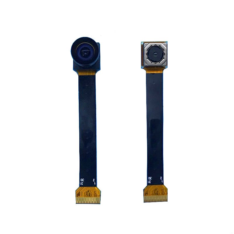
- Core specifications to evaluate
- Common embedded vision applications
- Building an OEM camera specification
- Prototyping, validation and production
- Frequently asked questions
What Is a MIPI Camera Module?
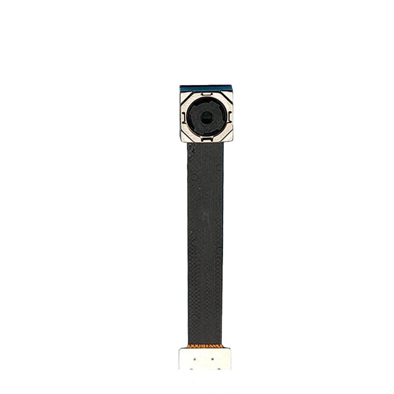
A MIPI camera module is a board-level imaging assembly that sends image data to a host processor through the MIPI Camera Serial Interface, most commonly CSI-2. A typical module combines a CMOS image sensor, lens, printed circuit board, clock and power components, control lines and a compact board-to-board or flexible-cable connector. Unlike a USB camera, it normally does not present itself as a complete peripheral. The host processor must support the sensor, receive the CSI-2 stream and process the raw or preprocessed image data.
This tighter integration is one reason MIPI modules can be compact and power-efficient. It is also why compatibility cannot be assumed from the connector alone. Two modules may use similar physical connectors while differing in lane count, voltage levels, clocking, pin assignment, sensor initialization, Bayer pattern, data format or driver requirements. A successful design therefore begins with the processor platform and supported camera pipeline, not only with the desired megapixel rating.
CBRITECH organizes these products within its MIPI Camera Module collection, where engineers can compare sensor, resolution and optical configurations for embedded projects. Related board-level options are also available in the broader CMOS Sensor Camera Module range.
Why OEM Teams Choose MIPI CSI-2
- Compact integration: The sensor can sit close to the processor or connect through a short flexible cable, helping product designers reduce enclosure volume.
- High data throughput: Multiple differential lanes support high-resolution and high-frame-rate image streams without the overhead of a general-purpose external bus.
- Low latency: Direct transfer into the processor image pipeline is valuable for robotics, visual feedback and real-time inference.
- Power efficiency: MIPI is designed for embedded and mobile electronics where energy consumption and heat generation must be controlled.
- Access to the processor ISP: The system can use the host image signal processor for demosaicing, exposure, white balance, noise reduction and color tuning.
- Flexible product architecture: The same processor platform may support different sensors if drivers, lane configurations and ISP tuning are properly managed.
These advantages come with additional engineering responsibility. A UVC-compatible USB module can often be tested quickly on a PC, while a MIPI design may require a sensor driver, device-tree configuration, clock settings, regulator sequencing and ISP calibration before the first usable image appears. MIPI is therefore most attractive when the product needs compact integration and controlled performance, and the development team can manage the camera pipeline.
How the Camera-to-Processor Pipeline Works
The lens focuses light onto the CMOS sensor, where each pixel converts light into an electrical signal. The sensor reads the pixel array, applies its internal timing and gain controls, and transmits image data through one or more CSI-2 lanes. A separate I2C or similar control interface is typically used to configure exposure, gain, frame timing and operating modes.
At the host, the CSI receiver reconstructs the stream and forwards it to the processor’s image pipeline. If the sensor outputs raw Bayer data, the ISP may perform demosaicing, white balance, color correction, lens shading correction, noise reduction, gamma and sharpening. The processed frames can then be encoded, displayed or passed to an AI model.
This division of responsibility matters when evaluating image quality. The sensor determines fundamental characteristics such as pixel size, quantum efficiency, read noise, dynamic range and shutter architecture. The lens determines field of view, distortion, aperture and focus. The ISP and tuning determine how the raw signal is converted into a usable image. Changing only one element may not solve a system-level problem.
Understanding CSI-2 Lanes and Bandwidth
MIPI CSI-2 commonly uses one, two or four data lanes together with a clock lane, depending on the sensor and host. More lanes can provide greater throughput, but the usable configuration must be supported by both sides. Resolution alone does not determine bandwidth. Frame rate, bit depth, blanking intervals, HDR modes and embedded metadata also contribute to the data rate.
An engineer should confirm the exact output mode rather than assuming that a four-lane connector guarantees maximum performance. A sensor may support several combinations, such as four lanes at a lower per-lane rate or two lanes at a higher rate. The processor may impose its own lane-speed limits, virtual-channel restrictions or supported data types.
MIPI Versus USB and DVP Camera Modules
| Selection Factor | MIPI CSI-2 | USB/UVC | DVP/Parallel |
| Best fit | Compact embedded products | PCs, industrial computers and fast prototypes | Lower-resolution MCUs and simpler embedded designs |
| Integration effort | Higher; driver and platform support required | Often lower with UVC | Moderate; parallel pin count and timing matter |
| Latency | Low when well integrated | Depends on bridge, format and host stack | Low, but limited by bus and MCU capability |
| Physical design | Small connector and few high-speed lanes | Cable and USB controller required | More signal pins and larger routing footprint |
| Image processing | Usually host ISP | Often module/bridge plus host | Sensor or host, depending on design |
USB is often the better choice when a camera must connect to a PC, industrial computer or replaceable external host. Teams that value rapid software integration can compare CBRITECH’s USB Camera Modules. DVP remains useful for cost-sensitive designs or microcontrollers that already expose a parallel camera interface; compatible options are available within the DVP Camera Module collection. The correct interface is the one that fits the processor, mechanical design and development resources of the final product.
Core Specifications to Evaluate Before Selecting a Module
1. Sensor Resolution, Pixel Size and Frame Rate
Megapixels describe spatial resolution, but they do not describe low-light performance, motion accuracy or algorithm suitability. A higher-resolution sensor creates more data and may require additional CSI bandwidth, memory bandwidth and processing power. Define the smallest feature that must be detected, the field of view and the working distance before choosing a resolution.
Pixel size also matters. Larger pixels can collect more light, although final sensitivity depends on sensor technology, lens aperture, exposure and processing. For dim scenes, test the actual illumination spectrum and motion conditions rather than relying only on a sensitivity claim.
2. Rolling Shutter or Global Shutter
Rolling-shutter sensors expose image rows at slightly different times. They are common and can provide excellent resolution and sensitivity for stationary or moderate-motion scenes. Fast motion may produce skew or geometric distortion. Global-shutter sensors capture the active frame at the same exposure moment and are better suited to robot guidance, barcode capture, conveyor inspection and measurement of moving objects.
Projects where motion accuracy is essential should review dedicated Global Shutter Camera Modules rather than assuming interface speed alone will prevent distortion.
3. Lens, Field of View and Focus
The lens determines how many useful pixels reach the target. A wide-angle lens captures more of the scene but assigns fewer pixels to a small object and may introduce distortion. A narrow field of view provides more detail at distance but requires accurate placement. Specify horizontal or vertical field of view at a defined working distance instead of using broad terms such as “wide-angle.”
Fixed focus is stable when subject distance is controlled. Autofocus helps when the distance changes, but adds moving parts, control logic and settling time. For calibrated inspection systems, a locked focus position may be preferable.
4. ISP, Color Tuning and Low-Light Behavior
A sensor can produce very different images on two processor platforms because the ISP tuning is different. Exposure, gain, white balance, color matrices, gamma, denoising, sharpening and anti-flicker behavior should be tuned for the actual application. Evaluation in a bright office is not enough if the product will operate under warehouse LEDs, outdoors or beside reflective machinery.
Systems that require black-and-white sensitivity or measurement consistency can also compare Monochrome Camera Modules. Day/night products should evaluate IR-cut filter behavior, infrared response and illumination wavelength as part of the complete optical design.

5. Platform and Driver Compatibility
Before ordering samples, confirm that the target processor supports the sensor, lane count, data format and clocking mode. Linux support may require a V4L2 subdevice driver, device-tree entries and platform-specific ISP files. A development board accepting a physical cable does not guarantee that the operating-system image contains the required driver or tuning.
For platforms such as NVIDIA Jetson, Raspberry Pi, Rockchip or other embedded Linux systems, ask whether the module has been validated on the exact board and software release. Compatibility statements should include supported resolutions, frame rates and control functions, not only whether an image was displayed once.
Common Embedded Vision Applications
Robotics and Autonomous Equipment
Robots use MIPI cameras for navigation, object recognition, human-machine interaction and manipulation. Direct processor integration supports low-latency perception, but the design must account for vibration, synchronized capture, exposure changes and the movement of both camera and subject. Stereo or multi-camera systems also need careful timing and calibration.
Edge AI and Smart Devices
AI appliances depend on consistent image input. A model trained on stable images may lose accuracy when production units have different lenses, exposure tuning or color response. Camera specifications should therefore include optical and image-quality acceptance limits, not only electronics. The camera, ISP and model should be validated as one pipeline.
Industrial Inspection
MIPI modules can be integrated into compact inspection heads, embedded controllers and smart tools. Repeatable lighting and optical geometry are often more important than maximum resolution. When parts move quickly, global shutter and trigger timing become central. When surfaces are reflective, polarizers or controlled illumination may be required.
Medical and Laboratory Equipment
Medical and laboratory products may require compact packaging, low heat, accurate color, controlled focus and long component availability. The camera component does not by itself make a product medically compliant, but the supplier should support documentation, revision control and stable production. For narrow cavities and distal-tip designs, specialized Endoscope Camera Modules may be more appropriate than a conventional board-level MIPI module.
Drones, Agriculture and Outdoor Systems
Compact size and low power make MIPI attractive for drones and battery-powered equipment. Outdoor imaging introduces rapid changes in sunlight, vibration, moisture and temperature. Visible-light modules can support navigation and crop analysis, while heat-pattern detection requires a dedicated Thermal Camera Module Core. Thermal and visible sensors answer different questions and should be selected according to the required measurement.
How to Build an OEM MIPI Camera Specification
A useful request for quotation should describe the application and host platform before listing a preferred sensor. This allows the supplier to identify incompatible assumptions early and recommend a module that fits the full system.
- Application and target: What feature, object, person or area must the camera capture?
- Host platform: Processor, development board, operating-system version and available CSI receiver.
- Image mode: Resolution, frame rate, bit depth, Bayer format and HDR requirements.
- Lane configuration: Required lane count, clocking mode and connector pinout.
- Optics: Working distance, field of view, focus range, distortion and lens-mount limits.
- Lighting: Indoor, outdoor, infrared, backlit, flickering or controlled illumination.
- Motion: Camera movement, target speed and tolerance for rolling-shutter distortion.
- Mechanical envelope: PCB dimensions, mounting points, connector orientation and cable routing.
- Environment: Temperature, vibration, dust, moisture and cleaning requirements.
- Commercial plan: Sample quantity, annual volume, lifecycle and production schedule.
OEM and ODM Customization Options
A standard sample is useful for proving processor compatibility and basic image quality, but production hardware often requires changes. Depending on the project, CBRITECH can evaluate PCB outline, mounting-hole positions, connector type, flexible-cable length, lens, field of view, focus distance, sensor orientation, firmware settings and image tuning.
Customization should be controlled through drawings, approved samples and revision records. A small change in sensor register settings or lens position may affect an AI model or measurement system even when the image still appears acceptable to a human operator. Production programs should therefore define golden samples, firmware identification and change-notification procedures.
Prototyping, Validation and Mass Production
- Confirm power sequencing, reset behavior and sensor initialization after repeated starts.
- Validate all required resolutions, frame rates, lane configurations and controls.
- Test frame stability, dropped frames and recovery from CSI or application errors.
- Evaluate image quality across minimum and maximum lighting conditions.
- Test focus consistency, lens retention, vibration and enclosure effects.
- Measure temperature rise during continuous operation inside the actual product.
- Validate the production operating-system image, driver and ISP tuning files.
- Compare multiple pilot units to confirm optical and image-quality consistency.
A successful engineering sample does not automatically prove production readiness. Component availability, approved alternates, software revision control and supplier change management should be reviewed before the camera is frozen into a long-life product.
Common Selection Mistakes to Avoid
- Choosing a sensor before confirming processor and driver support.
- Assuming identical connectors mean identical pinouts or compatibility.
- Selecting resolution without calculating bandwidth and host processing load.
- Ignoring ISP tuning and evaluating only raw sensor specifications.
- Using a rolling shutter for fast motion without application testing.
- Leaving lens and field-of-view decisions until after the enclosure is designed.
- Approving one sample without checking pilot-batch consistency and lifecycle risk.
Why Work With CBRITECH for an OEM MIPI Camera Project?
CBRITECH supplies board-level camera modules across MIPI, USB, DVP, feature-specific, endoscope and thermal categories. This broader portfolio helps engineering teams compare architectures instead of forcing every project into one interface or sensor family.
The most useful supplier conversation begins with the processor platform, target scene, mechanical drawing, lighting, frame-rate requirement and expected production volume. With those inputs, the team can help identify a suitable reference design and determine whether lens, PCB, connector or image-tuning changes are needed.
Start by reviewing the available MIPI Camera Modules and share the host platform and application requirements with CBRITECH before finalizing the camera architecture.
Frequently Asked Questions
What is the difference between MIPI CSI-2 and USB?
MIPI CSI-2 is a direct embedded sensor interface that normally requires processor, driver and ISP support. USB cameras behave as peripherals and may offer easier integration through UVC. MIPI is usually preferred for compact, low-power products; USB is often preferred for PCs and rapid prototypes.
Does a MIPI camera module work with any processor?
No. The processor must support the sensor data format, lane count and clocking, and the software stack must include a compatible driver and image pipeline. Physical connector compatibility alone is not sufficient.
How many MIPI lanes are required?
It depends on resolution, frame rate, bit depth, blanking and the supported lane speed of both sensor and host. One, two or four lanes are common. The exact output mode should be calculated and validated.
Is a global shutter required for robotics?
Not always. Rolling shutter can work well for stationary scenes or moderate motion. Global shutter is preferred when rapid movement would distort geometry or affect positioning accuracy.
Can MIPI camera modules be customized?
Yes. Possible changes include PCB dimensions, connector, cable, lens, field of view, focus distance, sensor orientation, image settings and mechanical mounting. Feasibility depends on volume, schedule and selected components.
What information should be sent to a camera-module supplier?
Provide the processor, operating system, CSI interface, image mode, working distance, field of view, lighting, motion, mechanical limits, environmental requirements and expected production volume.
Choose the Camera as Part of the Complete System
A MIPI camera module should not be selected as an isolated sensor board. Its performance depends on the processor, driver, ISP, optics, lighting, mechanical design and production controls around it. The best module is the one that delivers repeatable, usable images within the electrical, software, environmental and commercial limits of the finished product.
Defining those limits before sample selection reduces debugging, shortens prototype cycles and prevents late-stage redesigns. For a new robotics, AI, medical or industrial embedded vision project, CBRITECH can help evaluate a reference MIPI module and plan the customization required for the intended product.