Author: Opti Bridge Solutions

640×512 Thermal Imaging Camera Modules
thermal imaging cameras
Opti Bridge Solutions

640×512 Thermal Imaging Camera Modules: Choosing the Right Thermal Core for Drones, FPV and Embedded Vision

Thermal imaging changes what a vision system can detect. A conventional visible-light camera depends on reflected light from the environment. A thermal imaging system instead detects infrared radiation associated with temperature differences, making it useful for applications where ordinary visible-light imaging may be limited by darkness or where detecting heat patterns is more important than reproducing natural colors. For engineers developing drones, FPV platforms, thermal monoculars and specialized embedded vision equipment, the challenge is therefore not simply finding a thermal imaging camera. The real challenge is selecting a thermal core with the right combination of resolution, sensitivity, frame rate, physical size, weight, output interface, lens and operating characteristics. CBRITECH’s 640×512 thermal imaging camera core is designed around this type of integration. It combines a 640×512 infrared detector with a compact 20 × 20 mm module architecture and supports drone and thermal-monocular applications. This guide explains the technical factors OEMs and system developers should consider when selecting thermal imaging hardware for drones and embedded vision systems. What Is a Thermal Imaging Camera? A thermal imaging camera creates an image from infrared energy rather than depending solely on visible light. This difference is particularly important when the imaging objective involves detecting heat signatures or operating in conditions where ordinary cameras do not have enough visible illumination. The core of the system is its infrared detector. CBRITECH’s 640×512 module uses a vanadium oxide (VOx) uncooled infrared focal plane detector operating in the 8–14 μm band. For an OEM, the thermal core can become the imaging component inside a larger finished product rather than being a complete standalone camera. That makes the technology applicable to systems such as: thermal drones; FPV platforms; thermal monoculars; embedded infrared imaging equipment; remote observation systems; custom OEM thermal-imaging products. The correct module depends on what the complete system needs to detect and how the thermal video will be processed or displayed. Why 640×512 Resolution Matters Resolution is one of the first specifications engineers encounter when comparing thermal cameras. The target CBRITECH module provides a native thermal resolution of 640 × 512 pixels. That means the detector contains substantially more thermal-image information than lower-resolution alternatives. But resolution should not be considered in isolation. For OEM development, a useful thermal imaging system depends on the relationship between: resolution + detector sensitivity + lens + field of view + viewing distance + processing + output A higher detector resolution can provide more spatial information, but the final performance still depends on the complete optical and electronic design. This is why engineers should avoid choosing a thermal module purely because the number “640” looks better on a specification sheet. The actual application needs to define the specification. Understanding the 12 μm Pixel Pitch The module uses a 12 μm pixel spacing. Pixel pitch describes the distance between detector pixels. For engineers, this specification becomes relevant when considering detector architecture, optics, module dimensions and the overall imaging system. A thermal-camera design therefore needs to consider detector resolution and pixel pitch together rather than treating them as unrelated specifications. When evaluating an OEM thermal module, ask how the detector architecture works with the selected lens and intended viewing distance. That brings us to one of the most important parts of a thermal system: optics. Lens Selection Can Change the Entire Thermal Imaging System The same thermal core can behave very differently depending on the lens. CBRITECH lists a particularly broad lens range for this module: 4 mm, 5.3 mm, 7 mm, 9.1 mm, 13 mm, 15 mm, 19 mm, 25 mm, 35 mm and 50 mm. This gives OEM developers room to configure the imaging system around different application requirements. A shorter focal length may be appropriate where a broader scene needs to be observed, while longer focal lengths can be relevant where a narrower view or greater observation distance is required. That is particularly important when designing a thermal drone. A drone used for broad observation does not necessarily need the same optical configuration as a platform intended to observe a smaller target from farther away. Instead of asking: “Which thermal camera has the best lens?” OEM developers should ask: “Which lens gives our detector the field of view and observation characteristics required by our application?” That is a much more useful engineering question. Why Thermal Drones Need Purpose-Built Camera Modules Weight, dimensions, power consumption and video-interface compatibility become especially important when the camera is installed on an airborne platform. A thermal drone cannot simply carry unlimited imaging hardware. Every additional component affects the complete payload. CBRITECH lists its 640 thermal core at 20 × 20 mm excluding the lens and ≤23 g excluding the lens, with rated power consumption of ≤0.8 W. Those specifications make the physical integration discussion particularly relevant to drone developers. A thermal-drone designer should evaluate at least four areas together: Payload: Can the aircraft carry the camera, lens, mounting hardware and associated electronics without compromising the intended flight characteristics? Power: Can the onboard electrical architecture supply the camera reliably? Video transmission: Is the camera output compatible with the aircraft’s processing or transmission system? Optics: Does the selected lens provide the required view from the expected operating altitude or distance? Thermal-drone integration is therefore a system-engineering problem, not simply a camera-purchasing decision. Where an FPV Drone Camera Module Fits In FPV systems create another interesting camera requirement. An FPV drone camera module needs to deliver usable video to the pilot or downstream video system with an architecture compatible with the platform. CBRITECH’s thermal module supports CVBS output, and the product page also identifies USB support. Its listed analog format is PAL. This makes interface selection an important part of the buying decision. Not every FPV project requires thermal imaging. CBRITECH also offers a dedicated FPV WDR Drone Night Vision Camera for visible-light/low-light FPV applications. That model uses a 1/2.8-inch image sensor, CVBS output and a stated minimum illumination of 0.0001 lux. This distinction matters. Thermal FPV vs Low-Light FPV A thermal camera and a low-light camera solve different

Read More »
Compact Surveillance Camera Modules
Mini Camera Spy Cam
Opti Bridge Solutions

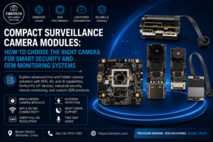
Compact Surveillance Camera Modules: How to Choose the Right Camera for Smart Security and OEM Monitoring Systems

Modern surveillance is moving far beyond traditional CCTV installations. Cameras are becoming smaller, smarter and easier to integrate into connected products, while businesses increasingly need remote access, wireless connectivity, AI-assisted monitoring and compact hardware that can fit inside purpose-built devices. That change has created demand for everything from the mini camera spy cam and spy camera wireless mini categories searched by end users to professional IP and embedded camera modules used by manufacturers, IoT developers and security-system integrators. For an OEM or product developer, however, choosing a camera should involve much more than finding the smallest available module. Image resolution, wireless connectivity, low-light performance, field of view, processing capabilities, storage, interfaces and customization can all determine whether a camera is suitable for the final product. This guide explains how modern compact surveillance camera technology works, what buyers should evaluate, and how different camera architectures can be matched with home, commercial and industrial monitoring applications. Why Surveillance Cameras Are Becoming Smaller and Smarter Traditional surveillance systems generally relied on relatively large cameras installed at fixed positions and connected to centralized recording equipment. That model still has an important place in security, but modern product development has created another requirement: cameras that can become part of the device itself. Compact camera technology can now be incorporated into smart-home products, access-control equipment, IoT systems, portable monitoring products, industrial equipment and other embedded electronics. For manufacturers, the important distinction is that a small camera module is not simply a miniature version of a CCTV camera. It can become an imaging component around which an entire product is developed. CBRITECH’s surveillance camera module range currently includes 4G, high-resolution IP and miniature WiFi solutions, providing different architectures for different monitoring requirements. What Is a Mini Camera Spy Cam? The phrase mini camera spy cam is commonly used when people search for extremely compact cameras designed for unobtrusive monitoring. From an engineering perspective, however, the more useful concept is a miniature surveillance camera module. Instead of focusing exclusively on whether a camera can be concealed, OEM buyers should consider whether its dimensions and architecture allow it to be integrated cleanly into the intended enclosure or finished product. Compact modules can be valuable where designers have limited internal space or need greater freedom over the final enclosure. Typical applications can include smart security products, portable monitoring equipment, IoT devices, access-control systems, equipment monitoring and custom surveillance products. This distinction is particularly important for manufacturers. The best hidden cameras for a consumer and the best miniature camera modules for an OEM product are not necessarily the same thing. Spy Camera Wireless Mini Technology: What Does Wireless Actually Add? One of the most commercially useful developments in compact surveillance has been wireless connectivity. A spy camera wireless mini search often reflects a simple buyer requirement: the user wants a small camera without being tied to a conventional wired surveillance installation. For product developers, WiFi can provide considerably more value. A WiFi-enabled camera architecture can support remote monitoring while reducing the need for dedicated video cabling. Depending on the hardware and software platform, this can enable smartphone or computer access and make the camera easier to incorporate into connected IoT products. CBRITECH’s 1080P IP Mini WiFi Camera Module, for example, uses a 1/2.7-inch CMOS sensor with 1920 × 1080 resolution and supports 802.11b/g/n WiFi and remote access. The module also provides TF-card storage support up to 64 GB and Android/Windows application compatibility, with iOS customization available. For developers evaluating a spy camera hidden WiFi architecture, these are more meaningful considerations than size alone. Important wireless-camera considerations include: network compatibility and stability; remote-access requirements; video resolution and frame rate; local versus remote storage; application/platform compatibility; power consumption; antenna and enclosure considerations; cybersecurity and access control. A compact WiFi module can therefore serve as the imaging foundation of a much larger connected-security product. Image Quality Still Comes First Making a camera smaller is useful only when the resulting image remains suitable for the intended application. Resolution is the most visible specification, but it should not be evaluated independently. A surveillance system may need to identify people or objects, monitor machinery, observe entrances, document events or simply provide general situational awareness. Each application creates different imaging requirements. Important factors include sensor size, resolution, frame rate, lens quality, field of view, dynamic range and low-light performance. For example, CBRITECH’s miniature WiFi module provides Full HD 1920 × 1080 output, configurable resolutions and a stated WDR specification above 100 dB. It also lists minimum illumination of 0.01 Lux at F1.2. The correct camera is therefore not automatically the one with the largest megapixel figure. The imaging system should be selected around the environment in which it actually needs to operate. Why Low-Light Performance Matters Security cameras rarely operate under perfect studio lighting. Entrances may contain strong backlighting. Warehouses may have dark corners. Outdoor environments change dramatically throughout the day. Industrial installations can combine bright machinery lights with shadowed areas. Low-light performance therefore deserves serious consideration when comparing compact surveillance modules. Dynamic range is equally important. A camera observing an entrance, for example, might simultaneously see a dark interior and a brightly illuminated exterior. Without adequate dynamic-range performance, important details can disappear into either shadows or highlights. OEM buyers evaluating hidden security cameras or embedded surveillance hardware should therefore look beyond headline resolution and examine how the complete imaging system performs under the lighting conditions expected in the final application. When an 8MP IP Camera Makes More Sense Miniaturization isn’t always the primary requirement. Applications requiring greater detail or more advanced edge intelligence may benefit from a more capable IP-camera architecture. CBRITECH’s 8MP IP camera supports resolution up to 3840 × 2160 and uses an embedded Linux architecture with a dual-core A53 processor and stated 2T INT8 computing capability. The product also supports smart events including human-figure motion detection, area intrusion and tripwire detection. Its interfaces include Ethernet, UART, USB and other connectivity options, while networking support includes protocols such as HTTP, TCP/IP, RTSP, RTP and

Read More »
ESP32-S3 USB Camera Modules
Opti Bridge Solutions

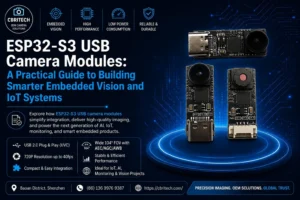
ESP32-S3 USB Camera Modules: A Practical Guide to Building Smarter Embedded Vision and IoT Systems

Modern embedded products increasingly need to do more than sense temperature, motion or location. They need to see. From smart monitoring equipment and compact IoT devices to image-recognition systems and AI-assisted prototypes, visual input is becoming an important part of embedded product development. But adding a camera to a compact embedded platform introduces a series of engineering decisions: sensor interface, wiring complexity, processor compatibility, image format, frame rate, lens selection and software integration all influence how quickly a concept can become a reliable product. For developers working with the ESP32 ecosystem, this is particularly important. Traditional camera implementations commonly rely on DVP-connected modules, but USB-based camera architectures provide another approach for projects where simplified connectivity, UVC support and easier integration are priorities. CBRITECH’s ESP32 Cam 720P USB Camera Module for Vision Development is designed around this requirement. The module combines a compact camera architecture with USB connectivity for ESP32-S3-oriented vision development, creating an option for engineers developing embedded AI, IoT vision, monitoring and image-recognition products. Why ESP32-S3 Is Becoming Important for Embedded Vision The requirements placed on embedded devices are changing. A traditional IoT node may only collect information from basic sensors. A modern vision-enabled device can potentially capture images or video and pass that visual data into software for detection, monitoring, classification or other computer-vision workflows. This creates opportunities in areas such as smart monitoring, connected devices, education and development platforms, AI vision prototypes and compact embedded products. But the camera becomes a critical part of the architecture. An embedded vision system is only as useful as the visual information supplied to it. Engineers therefore need to evaluate more than megapixels when selecting an ESP32 camera module. The interface, physical dimensions, field of view, frame rate, optical configuration and integration requirements can be just as important as nominal resolution. Traditional DVP Camera Modules vs USB Camera Modules Many developers associate ESP32 camera development with DVP camera modules such as OV2640-based designs. That architecture can be appropriate for many applications, but it requires the development platform to handle the camera’s parallel interface and associated signals. A USB camera changes the integration model. Rather than treating the image sensor primarily as a raw parallel camera peripheral, a USB camera module can package imaging and transmission functionality into a more standardized connection. CBRITECH specifically positions its module as an alternative to traditional OV2640, OV3660 and OV5640 DVP camera modules, with the objective of reducing wiring and hardware-debugging complexity in compatible ESP32-oriented vision systems. That distinction matters to OEM teams because development time is part of product cost. A lower-cost camera that requires extensive engineering work is not necessarily the lower-cost solution at the system level. What Is an ESP32-S3 USB Camera Module? An ESP32-S3 USB camera module is a compact imaging module intended to provide visual data through a USB-based architecture for ESP32-S3-oriented applications. CBRITECH’s current module uses a USB 2.0 interface and USB bus power at 5V. The product page also identifies standard UVC support and a Type-C interface. Its listed module dimensions are only 26 mm × 11 mm, making physical integration possible in compact products where PCB space is limited. For OEM developers, this combination is particularly useful when the goal is not merely to demonstrate a camera but to create a repeatable hardware architecture that can eventually move toward productization. 720P Resolution: Why More Megapixels Are Not Always Better It is easy to assume that higher resolution automatically means a better embedded camera. In reality, resolution should match the application’s actual visual requirements and processing budget. CBRITECH lists an active array of 1288 × 728 and supports 1280 × 720 output. The listed output configurations include: Output Maximum Listed Frame Rate 1280 × 720 40 fps 640 × 480 60 fps 320 × 240 120 fps The module supports YUV and MJPEG output formats. This gives developers an important engineering trade-off. A project that needs visual detail may prioritize 720P output. A vision algorithm that values responsiveness over resolution may instead operate at a lower resolution and higher frame rate. That flexibility can be more useful than simply specifying the highest possible megapixel count. Wide Field of View for Embedded Vision Lens selection determines what the camera actually sees. The module is specified with an approximately 104° field of view, a 1.5 mm effective focal length and F/2.2 optics. A wide field of view can be useful when a device needs to observe a comparatively broad scene from a short distance. Potential applications include compact monitoring equipment, IoT devices, educational vision systems, smart-device prototypes and certain machine-vision experiments. However, engineers should not choose a wide-angle camera simply because the number is larger. A narrower field may be preferable when the target occupies a small portion of the scene or when greater pixel density on a specific object is required. The correct lens is therefore an application-level decision, not merely a camera specification. Automatic Image Controls Embedded products often operate in environments where lighting cannot be perfectly controlled. The CBRITECH module lists automatic: AGC — Automatic Gain Control AEC — Automatic Exposure Control White Balance These functions can help the imaging system adapt to changing illumination without requiring the host application to manually control every image parameter. For prototypes, IoT devices and monitoring applications, this can simplify initial integration. For highly controlled industrial vision systems, however, engineers may still want to validate whether automatic exposure behavior is appropriate for the target algorithm. Computer vision frequently values image consistency differently from human viewing. UVC and Why It Matters One of the more commercially valuable characteristics of this product is its UVC-oriented architecture. USB Video Class provides a standardized framework for transmitting video over USB. CBRITECH states that its ESP32-oriented camera uses the standard UVC protocol and is intended to reduce the requirement for additional driver installation on supported host environments. For developers, this can reduce the amount of camera-specific software work required during evaluation. Instead of spending a large part of the prototype phase simply getting images out of

Read More »
4G IP Camera Modules
Opti Bridge Solutions

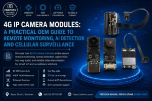
4G IP Camera Modules: A Practical OEM Guide to Remote Monitoring, AI Detection and Cellular Surveillance

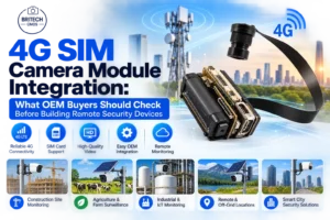
Traditional IP cameras work well when reliable Wi-Fi or wired network infrastructure is already available. But what happens when a product needs video connectivity in a location where fixed internet access is unavailable, inconvenient or unsuitable? That is where the 4G IP camera module becomes particularly valuable. By combining a camera, cellular connectivity, remote viewing and intelligent monitoring functions into an embedded architecture, a 4G camera module can help manufacturers develop portable security devices, remote monitoring equipment, connected surveillance systems and specialized OEM camera products without depending entirely on conventional local network infrastructure. CBRITECH’s 4G IP Camera Network Remote Control AI Dedicated Camera Module is designed around this requirement. The module supports a SIM card, remote monitoring, local TF-card storage, human detection, night vision, two-way audio and mobile access, while CBRITECH also offers different lens options and customized housings for OEM applications. For engineers and product developers, however, choosing a 4G camera should involve much more than asking whether the module accepts a SIM card. The imaging system, cellular architecture, storage, optics, remote software, power requirements, environmental conditions and OEM customization possibilities all need to be evaluated as part of the complete product. What Is a 4G IP Camera Module? A 4G IP camera module is an imaging system that combines camera functionality with IP-based video transmission and cellular connectivity. Instead of relying only on Ethernet or a local Wi-Fi network, a cellular-enabled camera can use a supported SIM/network connection to provide remote video functionality. This changes where connected cameras can potentially be deployed. For example, a conventional Wi-Fi camera normally needs to remain within an appropriate network environment. A 4G SIM camera module can be considered for products intended for more independent or portable deployment, provided cellular coverage and the rest of the system requirements are suitable. CBRITECH’s module is specifically designed for network remote monitoring and incorporates 4G cellular connectivity. The product also supports an all-in-one Wi-Fi network connection, giving OEM developers more flexibility when planning the final connectivity architecture. Why 4G Connectivity Matters for Remote Camera Systems The key advantage of 4G is not simply that it is “wireless.” Wi-Fi is wireless too. The important difference is network independence. A Wi-Fi camera generally needs access to a nearby router or wireless network. Cellular connectivity provides another path for products that need to communicate over greater geographic distances without being permanently tied to a particular local Wi-Fi installation. That makes a 4G remote monitoring camera relevant for product concepts involving remote locations, temporary installations, portable systems and other environments where conventional network infrastructure may be limited. From an OEM perspective, this can change the entire system design. Instead of asking: “How will the customer connect this camera to the local network?” the development team can evaluate: “Can the product establish its remote connection through an appropriate cellular network?” That can make deployment more flexible, although network availability, SIM/data plans, regional carrier compatibility and bandwidth requirements still need to be validated separately for the intended market. 1080P Imaging for Remote Monitoring Resolution is one of the first specifications buyers compare, but higher resolution is not automatically better for every remote camera. CBRITECH specifies a 2MP, 1920 × 1080 CMOS imaging system for this product. It also supports 1920 × 1080P, 1280 × 720P and 640 × 480P video output, with a listed frame rate of approximately 20–25 fps. This range gives developers options when balancing visual detail against bandwidth and storage requirements. For example, 1080P may be preferable when identifying scene details is important, while lower-resolution output may be useful where data transmission or storage efficiency has greater priority. This becomes especially important in a 4G system because video transmission consumes network data. The correct engineering decision is therefore not simply: “Use the highest resolution.” It is: “Use the resolution and bitrate that provide enough visual information for the application without unnecessarily increasing transmission and storage requirements.” CBRITECH lists a bitrate range of 32 KB–20 Mbps, giving developers another parameter to evaluate during system design. H.264 Video Encoding Video compression is particularly important for cellular cameras. Raw video requires substantial bandwidth, making efficient encoding essential for practical remote transmission. The CBRITECH module uses H.264 video encoding. For OEM developers, compression should be evaluated alongside resolution, frame rate, network conditions and required image quality. A remote surveillance system may not need maximum image quality continuously. Depending on the application, the system architecture may prioritize efficient monitoring and then preserve higher-quality footage when an important event occurs. The camera should therefore be treated as part of a complete video-data architecture rather than simply as an image sensor. Human Detection for Smarter Monitoring One of the most commercially important features of the product is human-form detection. CBRITECH lists human detection alongside functions such as alarms, customized investigation areas, human-shaped framing, image mirroring and DV mode. Why does this matter? Traditional surveillance systems can generate large quantities of footage. If every visual change is treated equally, the system may capture events that have little practical importance. Human detection can make monitoring more targeted by helping the system distinguish human presence as a meaningful event. For an OEM product developer, that creates opportunities to design smarter monitoring workflows around specific use cases. However, it is important not to overstate the capability. The CBRITECH page specifically confirms human-form detection; it does not claim advanced identity recognition or facial identification. Those are different technologies and should not be presented as equivalent. Night Vision for Low-Light Monitoring Remote cameras frequently need to operate beyond daylight hours. CBRITECH specifies 940 nm IR LEDs and night-vision functionality. The camera’s listed minimum illumination is RGB 0.01 Lux at F1.2. Infrared illumination can help a camera capture useful visual information when visible ambient lighting becomes insufficient. This makes night-vision capability particularly important for security and monitoring applications expected to operate continuously. When evaluating an OEM camera, however, developers should test night performance in the actual target environment. Indoor rooms, outdoor areas, narrow corridors and reflective surfaces can behave differently under

Read More »
Global Shutter vs Rolling Shutter Camera Modules: Which One Is Right for Your Embedded Vision System?
Camera Module
Opti Bridge Solutions

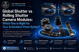
Global Shutter vs Rolling Shutter Camera Modules: Which One Is Right for Your Embedded Vision System?

A camera can deliver the correct resolution, interface and lens yet still produce unusable data when the subject starts moving. Barcode edges lean, rotating parts appear bent, a conveyor item changes shape across the frame, or a robot estimates the wrong object position. In many embedded vision projects, these failures are not caused by the algorithm. They begin with the way the image sensor exposes the scene. That is why shutter architecture should be treated as an early system decision rather than a specification checked after the sensor has been selected. Global shutter and rolling shutter sensors can both produce excellent images, but they capture time differently. The correct choice depends on scene motion, camera motion, exposure time, lighting, required accuracy, bandwidth, optics, processing platform and cost target. For OEM teams evaluating a global shutter camera module, the question is not whether global shutter is universally better. It is whether the application needs every active pixel to represent the same exposure interval. This guide explains that distinction and shows how engineers and procurement teams can select the appropriate architecture for robotics, inspection, logistics, medical equipment and other embedded systems. Contents Why shutter architecture matters How rolling shutter captures an image How global shutter captures an image Global shutter versus rolling shutter comparison Motion distortion and lighting interaction Application-based selection Interface, optics and processing considerations Building an OEM specification Prototyping and production validation Frequently asked questions Why Shutter Architecture Matters in Embedded Vision An image sensor does not capture an abstract scene; it samples a scene over time. If the subject and camera remain still during that sampling window, both shutter types can produce geometrically correct images. When movement occurs, the timing relationship between rows becomes important. For a human viewing ordinary video, mild rolling-shutter distortion may be acceptable or unnoticed. For a computer-vision system, a few pixels of geometric error can change a measurement, shift a detected edge, lower OCR confidence or cause a robot to pick beside the intended target. The shutter decision therefore affects not only visual quality but also the reliability of downstream software. The effect must also be evaluated together with exposure time. A global shutter can remove row-to-row timing distortion, but a long exposure can still create motion blur. Conversely, a fast rolling-shutter sensor operating with short exposure and limited motion may produce acceptable results. Shutter type, sensor readout speed, illumination and scene velocity form one system. How a Rolling Shutter Camera Module Works A rolling shutter exposes or reads the sensor sequentially, usually row by row. The top of the frame represents a slightly earlier moment than the bottom. Each row can have the same exposure duration, but its exposure begins and ends at a different time. When the scene is stationary, this timing offset does not change geometry. When an object moves across the field of view, its position changes while successive rows are being sampled. Vertical lines may lean, circular objects may appear oval, rotating blades may bend, and vibration may create a wobbling or gelatin-like effect. Rolling shutter remains a strong option for many products. Sensors using this architecture often provide attractive resolution, sensitivity, compact optical formats and cost efficiency. They are commonly suitable for document capture, conferencing, smart displays, microscopy, stationary inspection, access devices and applications in which motion is slow or controlled. A rolling shutter should therefore not be rejected simply because a product includes motion. Engineers should quantify the movement, direction, exposure time and acceptable geometric error. A faster row readout can reduce distortion, and controlled strobed lighting can sometimes freeze the scene sufficiently for a rolling-shutter sensor. How a Global Shutter Camera Module Works A global shutter begins and ends exposure for the active pixels at the same time. The stored signal is then read from the sensor after the exposure interval. Because the complete frame represents one shared moment, moving objects retain their geometry more accurately. This makes global shutter valuable for machine vision, robot guidance, barcode scanning, dimensional inspection, traffic imaging and other tasks in which object position or shape must be measured while the subject or camera is moving. Global shutter does not remove every imaging challenge. Fast motion may still blur if exposure is too long. High frame rate may require more interface bandwidth and host processing. Some global-shutter sensors may involve trade-offs in resolution, pixel size, sensitivity, sensor cost or availability compared with rolling-shutter alternatives. The technology should be selected because the application requires synchronized exposure, not because it sounds more advanced. CBRITECH’s Global Shutter Camera Modules include board-level options for high-speed and motion-sensitive applications. Projects requiring contrast-focused or machine-vision output can also compare Monochrome Camera Modules where color information is not required. Global Shutter vs Rolling Shutter: Practical Comparison Selection Factor Global Shutter Rolling Shutter Exposure timing All active pixels share the same exposure interval Rows are exposed/read sequentially Fast moving objects Preserves geometry more reliably May produce skew, wobble or bent shapes Stationary or slow scenes Works well Often works very well and may offer better value Typical strengths Motion accuracy, triggering, measurement, robotics Resolution, sensitivity, compact format, cost efficiency Lighting strategy Short exposures and strobes commonly used Can benefit strongly from controlled or pulsed illumination Common applications Machine vision, AMRs, scanning, metrology, traffic Document capture, smart devices, microscopy, fixed monitoring Engineering trade-offs May cost more or require more bandwidth Requires motion-risk assessment and readout validation Understanding Motion Distortion Skew If an object moves horizontally while rows are captured sequentially, vertical edges may lean. This is common when imaging vehicles, conveyor parts or a camera panning across a scene. Wobble and Vibration Artifacts When the camera vibrates, different rows record different camera positions. The image may appear to wobble even when individual frames remain sharp. This matters for drones, mobile robots and handheld equipment. Rotational Distortion Fans, wheels, propellers and rotating machine parts can appear curved or disconnected because their angular position changes during row readout. Algorithms trained on geometrically correct components may then misclassify the result. Motion Blur

Read More »
Medical Endoscope Camera Modules
Medical Endoscope Camera
Opti Bridge Solutions

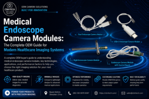
Medical Endoscope Camera Modules: The Complete OEM Guide for Modern Healthcare Imaging Systems

Introduction Medical imaging has transformed diagnosis and minimally invasive surgery. At the heart of every endoscope is a miniature imaging system that must deliver exceptional clarity while fitting into extremely compact devices. Selecting the right medical endoscope camera module requires balancing sensor performance, optics, integration, reliability, and long-term manufacturability. Modern OEMs increasingly require customized camera solutions that support AI-assisted diagnostics, HD imaging, and compact medical equipment. Why Medical Endoscope Camera Modules Matter High-quality imaging improves diagnostic confidence, procedural efficiency, and patient outcomes. Poor image quality can reduce visibility, increase procedure time, and affect clinical decision-making. Modern camera modules are therefore engineered to provide excellent color reproduction, low-light performance, stable video, and compact integration. Understanding the Camera Module A medical endoscope camera module integrates a CMOS image sensor, precision optics, PCB, flexible cable, connector, and supporting electronics into a miniature package capable of transmitting high-quality images to the host system. How It Works Light enters through precision optics, reaches the CMOS sensor, is converted into digital data, processed by the ISP for white balance, exposure, noise reduction, and color correction, then displayed in real time for the clinician. Choosing the Right Sensor Resolution, pixel size, sensitivity, frame rate, shutter type, and lifecycle support should all be evaluated. The ideal sensor depends on the intended medical application rather than simply having the highest megapixel count. Flexible vs Rigid Endoscopes Flexible systems prioritize miniature dimensions and cable flexibility for gastrointestinal and pulmonary procedures, while rigid systems emphasize optical precision and image quality for laparoscopic and arthroscopic surgery. Disposable vs Reusable Disposable devices reduce cross-contamination risks, whereas reusable systems focus on long-term durability and sterilization compatibility. OEM Customization Manufacturers often require custom lens selection, PCB dimensions, connector orientation, ribbon cable length, ISP tuning, housing design, and interface compatibility to meet product requirements. Engineering Challenges Signal integrity, thermal management, optical alignment, EMC, sterilization, miniature packaging, and component lifecycle management are major engineering considerations. AI in Endoscopy AI-assisted detection, image enhancement, lesion identification, and workflow automation are increasing the importance of consistent, high-quality imaging data. Conclusion The best medical endoscope camera module is one that matches the complete system design. By combining the appropriate sensor, optics, customization, and engineering support, OEMs can build reliable next-generation healthcare imaging products. FAQs What is a medical endoscope camera module? A miniature imaging system integrated into endoscopes for diagnostic and surgical visualization. Can camera modules be customized? Yes. Sensor, optics, PCB, cable, connector, firmware, and image tuning can all be customized for OEM projects. Which interface should I choose? MIPI is preferred for embedded medical devices, while USB is suitable for external systems and rapid prototyping. Call to Action Developing a next-generation medical imaging device? Contact CBRITECH to discuss customized medical endoscope camera modules designed for your OEM requirements.

Read More »
USB Camera Modules: The Complete OEM Buyer's Guide for Industrial and Embedded Vision Systems
USB Camera Module
Opti Bridge Solutions

USB Camera Modules: The Complete OEM Buyer’s Guide for Industrial and Embedded Vision Systems

A camera module can look simple from the outside: a sensor, a lens, a circuit board and a cable. In a finished product, however, it becomes the visual input for an entire system. It may need to identify a face in uneven lighting, inspect a moving component, capture a document without distortion or deliver stable video inside a medical device. The quality of that visual input affects every decision the system makes afterward. For many original equipment manufacturers, a USB camera module provides the most practical route from imaging concept to working product. USB connectivity is familiar, widely supported and easier to integrate than many board-level interfaces. When the module follows the USB Video Class standard, a compatible host can often recognize it through an existing driver, reducing the amount of software development required during prototyping and deployment. That convenience does not make every USB camera interchangeable. Resolution, sensor architecture, shutter type, frame rate, lens, image signal processing, cable design, heat management and mechanical dimensions all influence whether a module will work reliably in the final device. This guide explains how engineers, sourcing teams and product managers can evaluate those factors before selecting an off-the-shelf module or requesting an OEM design. Contents What is a USB camera module? Why OEM teams choose USB for embedded vision How a USB camera module works USB 2.0 versus USB 3.0 Core specifications to evaluate Rolling shutter versus global shutter Common industrial and embedded applications How to build an OEM camera specification Prototyping, validation and mass production Frequently asked questions What Is a USB Camera Module? A USB camera module is a compact imaging assembly that sends video or still-image data to a host through a USB connection. A typical design combines a CMOS image sensor, lens, printed circuit board, image signal processor or bridge controller, memory, clock components, power regulation and a USB cable or connector. Depending on the design, the board may also support microphones, LEDs, infrared illumination, motorized focus or additional control inputs. The key difference between an OEM camera module and a consumer webcam is its intended method of integration. A webcam is a finished accessory. A module is a component that can be installed inside another product, adapted to a custom enclosure and tuned for a defined viewing distance, lighting condition and processing workflow. It can therefore be designed around the requirements of a kiosk, robot, scanner, laboratory instrument, access terminal or industrial inspection station. Many USB modules use UVC, or USB Video Class, which allows supported operating systems to communicate with the camera through a standard video-device framework. This can simplify development on Windows, Linux and Android platforms, although compatibility still needs to be tested on the exact host board, operating-system build and application stack used in production. Why OEM Teams Choose USB for Embedded Vision USB is attractive when a product requires a direct connection to a PC, industrial computer, single-board computer or embedded host with a usable USB port. Instead of routing a short-range sensor interface directly into a processor, the camera module handles part of the image pipeline and presents itself as a peripheral. This often shortens the path from evaluation sample to functional prototype. Faster integration: UVC-compatible modules can reduce driver work and allow early testing with common capture software or standard video APIs. Flexible placement: A cable allows the optical assembly to be positioned away from the host processor, which is useful in kiosks, robots and larger instruments. Broad host support: USB is available on many industrial PCs, mini PCs, edge computers and development boards. Useful resolution range: USB camera boards are available from compact VGA designs to high-resolution and high-frame-rate modules. Practical customization: Manufacturers can adjust the PCB shape, connector, cable, lens, focus range, firmware and image tuning without redesigning the entire host platform. USB is not automatically the correct interface for every product. Very small mobile devices, tightly integrated consumer electronics and designs that connect a sensor directly to a system-on-chip may be better served by MIPI camera modules. USB becomes especially compelling when development speed, host compatibility, cable reach and replaceable modular hardware matter more than achieving the smallest possible electronics footprint. How a USB Camera Module Works The imaging process begins when the lens directs light onto the sensor. The sensor converts light into electrical signals, which are read as pixel data. The signal then passes through processing stages that can include demosaicing, exposure control, white balance, noise reduction, sharpening, color correction and compression. A USB controller packages the resulting stream for transmission to the host. The host enumerates the camera when it is connected, identifies the supported video formats and exposes those options to the application. The application may then request a specific resolution, frame rate and pixel format. Actual performance depends on the complete data path: sensor output, internal processing, USB controller, cable, host port, CPU load, memory bandwidth and application design. The image sensor remains one of the most important components. CBRITECH groups board-level products within its CMOS sensor camera module range, where different sensor and interface combinations can be considered for compact embedded products. Sensor selection should be based on more than megapixels; pixel size, dynamic range, sensitivity, shutter architecture and availability may be more important to the final result. USB 2.0 Versus USB 3.0 Camera Modules The interface version determines the amount of transmission headroom available, but the name printed on the module does not tell the whole story. USB 2.0 is often sufficient for standard-resolution video, compressed formats and applications where cost and compatibility are more important than maximum throughput. USB 3.0 provides substantially more bandwidth and is usually preferred for higher resolution, higher frame rates, lower latency or less-compressed image data. Selection Factor USB 2.0 USB 3.0 Typical fit Standard HD video, compressed streams, cost-sensitive products High-resolution, high-frame-rate and lower-latency imaging Bandwidth headroom Limited for uncompressed high-resolution output Better suited to larger data streams Host availability Very broad Requires a suitable USB 3.x host path Cable and layout sensitivity Generally easier

Read More »
MIPI Camera Modules Explained: The Complete OEM Guide for Embedded Vision, AI and Industrial Applications
MIPI camera module
Opti Bridge Solutions

MIPI Camera Modules Explained: The Complete OEM Guide for Embedded Vision, AI and Industrial Applications

When an OEM begins developing an embedded vision product, the camera interface becomes an architectural decision rather than a simple component choice. It affects PCB layout, processor selection, power consumption, image latency, software development, thermal behavior and the space available inside the enclosure. A sensor with excellent laboratory performance can still become the wrong choice if its interface does not match the host platform or if the image pipeline cannot be supported in production. For compact systems that connect the image sensor directly to an application processor, a MIPI camera module is often the most efficient option. MIPI CSI-2 transfers image data over high-speed differential lanes, allowing high-resolution video to move from the sensor to the processor with low overhead and a small physical footprint. This architecture is common in smartphones, but it is equally relevant to robotics, edge AI devices, medical instruments, smart access products, drones and industrial embedded systems. MIPI is not automatically better than USB or DVP. It usually requires closer coordination between the camera module, processor, device tree, driver, image signal processor and PCB design. The engineering advantage appears when those elements are planned together. This guide explains how OEM teams can evaluate MIPI camera modules, identify integration risks early and build a specification that supports both prototype performance and long-term production. Contents What is a MIPI camera module? Why OEM teams choose MIPI CSI-2 How the camera-to-processor pipeline works MIPI versus USB and DVP Core specifications to evaluate Common embedded vision applications Building an OEM camera specification Prototyping, validation and production Frequently asked questions What Is a MIPI Camera Module? A MIPI camera module is a board-level imaging assembly that sends image data to a host processor through the MIPI Camera Serial Interface, most commonly CSI-2. A typical module combines a CMOS image sensor, lens, printed circuit board, clock and power components, control lines and a compact board-to-board or flexible-cable connector. Unlike a USB camera, it normally does not present itself as a complete peripheral. The host processor must support the sensor, receive the CSI-2 stream and process the raw or preprocessed image data. This tighter integration is one reason MIPI modules can be compact and power-efficient. It is also why compatibility cannot be assumed from the connector alone. Two modules may use similar physical connectors while differing in lane count, voltage levels, clocking, pin assignment, sensor initialization, Bayer pattern, data format or driver requirements. A successful design therefore begins with the processor platform and supported camera pipeline, not only with the desired megapixel rating. CBRITECH organizes these products within its MIPI Camera Module collection, where engineers can compare sensor, resolution and optical configurations for embedded projects. Related board-level options are also available in the broader CMOS Sensor Camera Module range. Why OEM Teams Choose MIPI CSI-2 Compact integration: The sensor can sit close to the processor or connect through a short flexible cable, helping product designers reduce enclosure volume. High data throughput: Multiple differential lanes support high-resolution and high-frame-rate image streams without the overhead of a general-purpose external bus. Low latency: Direct transfer into the processor image pipeline is valuable for robotics, visual feedback and real-time inference. Power efficiency: MIPI is designed for embedded and mobile electronics where energy consumption and heat generation must be controlled. Access to the processor ISP: The system can use the host image signal processor for demosaicing, exposure, white balance, noise reduction and color tuning. Flexible product architecture: The same processor platform may support different sensors if drivers, lane configurations and ISP tuning are properly managed. These advantages come with additional engineering responsibility. A UVC-compatible USB module can often be tested quickly on a PC, while a MIPI design may require a sensor driver, device-tree configuration, clock settings, regulator sequencing and ISP calibration before the first usable image appears. MIPI is therefore most attractive when the product needs compact integration and controlled performance, and the development team can manage the camera pipeline. How the Camera-to-Processor Pipeline Works The lens focuses light onto the CMOS sensor, where each pixel converts light into an electrical signal. The sensor reads the pixel array, applies its internal timing and gain controls, and transmits image data through one or more CSI-2 lanes. A separate I2C or similar control interface is typically used to configure exposure, gain, frame timing and operating modes. At the host, the CSI receiver reconstructs the stream and forwards it to the processor’s image pipeline. If the sensor outputs raw Bayer data, the ISP may perform demosaicing, white balance, color correction, lens shading correction, noise reduction, gamma and sharpening. The processed frames can then be encoded, displayed or passed to an AI model. This division of responsibility matters when evaluating image quality. The sensor determines fundamental characteristics such as pixel size, quantum efficiency, read noise, dynamic range and shutter architecture. The lens determines field of view, distortion, aperture and focus. The ISP and tuning determine how the raw signal is converted into a usable image. Changing only one element may not solve a system-level problem. Understanding CSI-2 Lanes and Bandwidth MIPI CSI-2 commonly uses one, two or four data lanes together with a clock lane, depending on the sensor and host. More lanes can provide greater throughput, but the usable configuration must be supported by both sides. Resolution alone does not determine bandwidth. Frame rate, bit depth, blanking intervals, HDR modes and embedded metadata also contribute to the data rate. An engineer should confirm the exact output mode rather than assuming that a four-lane connector guarantees maximum performance. A sensor may support several combinations, such as four lanes at a lower per-lane rate or two lanes at a higher rate. The processor may impose its own lane-speed limits, virtual-channel restrictions or supported data types. MIPI Versus USB and DVP Camera Modules Selection Factor MIPI CSI-2 USB/UVC DVP/Parallel Best fit Compact embedded products PCs, industrial computers and fast prototypes Lower-resolution MCUs and simpler embedded designs Integration effort Higher; driver and platform support required Often lower with UVC Moderate; parallel pin count

Read More »
Mini Camera Spy Cam Technology: What to Look for in Modern Wireless Monitoring Systems
Mini Camera Spy Cam
Opti Bridge Solutions

Mini Camera Spy Cam Technology: What to Look for in Modern Wireless Monitoring Systems

Compact cameras have evolved significantly over the past few years. What was once limited to bulky CCTV equipment can now fit into devices small enough to be integrated into smart home products, industrial monitoring systems, portable electronics, and IoT applications. As a result, many users searching for a mini camera spy cam, best hidden cameras, or a spy camera wireless mini solution are often looking for a combination of image quality, wireless connectivity, and flexible integration options rather than simply a smaller camera. The challenge is finding a camera module that delivers reliable video performance while maintaining a compact form factor. Why Miniature WiFi Cameras Are Growing in Popularity Modern monitoring systems are no longer restricted to fixed security installations. Businesses and developers increasingly require cameras that can be integrated into custom products, portable devices, remote monitoring systems, and smart automation projects. A compact spy camera hidden WiFi module can provide several advantages: Flexible installation options Wireless video transmission Remote monitoring capability Reduced wiring requirements Integration into compact electronic devices Support for mobile and desktop applications These features make miniature WiFi cameras useful across a wide range of environments, from smart home systems to industrial monitoring platforms. What Defines a High-Quality Mini Camera Module? Many small cameras look similar on paper, but several technical factors have a direct impact on real-world performance. Full HD Video Resolution Image quality remains one of the most important considerations. The Shenzhen Brilliant CMOS Technology 1080P IP Mini WiFi Camera Module utilizes a 2MP image sensor capable of recording at 1920 × 1080 resolution. Full HD video helps preserve details that may be difficult to identify with lower-resolution cameras. For monitoring applications, clearer images often lead to better visibility and improved situational awareness. Low-Light Performance Many monitoring environments operate in less-than-ideal lighting conditions. With a minimum illumination rating of 0.01Lux@F1.2, the module is designed to maintain image visibility even in darker environments where standard cameras may struggle. Wide Dynamic Range Lighting conditions can change dramatically throughout the day. The module’s WDR performance of more than 100dB helps balance bright and dark areas within the same scene, improving image clarity when dealing with windows, doorways, or mixed lighting environments. Wireless Connectivity for Greater Flexibility One of the biggest advantages of a spy camera wireless mini system is the ability to transmit video without extensive cabling. The module supports 802.11b/g/n WiFi communication and remote access functionality, allowing users to view live video streams from connected devices. This wireless capability makes the camera suitable for: Smart home security systems Portable monitoring devices IoT applications Remote observation projects Mobile surveillance platforms By reducing wiring complexity, deployment becomes faster and more flexible. Compact Design Without Sacrificing Performance Size is often a critical factor when integrating cameras into custom products. The Shenzhen Brilliant CMOS Technology WiFi camera module features a compact design with customizable FPC interfaces and configurable cable lengths, making it easier to integrate into space-constrained environments. Additional customization options include: Field of view options from 60° to 200° Custom FPC lengths Optional audio support TF card storage support up to 64GB Android and Windows application compatibility These options allow developers to tailor the camera to specific project requirements. Multi-Camera Synchronization Capabilities Many applications require multiple cameras working together. Unlike standard single-camera systems, Shenzhen Brilliant CMOS Technology supports multi-camera synchronization solutions with four or more cameras operating simultaneously. This capability is useful for: Multi-angle monitoring systems Industrial observation platforms Robotics projects Smart transportation solutions Advanced imaging applications USB UVC multi-camera synchronization options are also available for projects that require coordinated image capture across multiple viewpoints. Common Applications Smart Home Security Many homeowners searching for the best hidden cameras prioritize compact size, remote access, and reliable video quality. The module’s WiFi connectivity and Full HD resolution make it suitable for modern home monitoring systems. Industrial Monitoring Factories and warehouses often require discreet monitoring of equipment, production processes, and restricted-access areas. The module’s compact design allows integration into existing systems without major modifications. IoT Devices As connected devices become more common, miniature camera modules are increasingly used in smart appliances, automation systems, and remote monitoring products. Drones and Portable Electronics The combination of compact dimensions, low power consumption, and wireless connectivity makes the module suitable for mobile platforms where weight and space are important considerations. Why Shenzhen Brilliant CMOS Technology? When selecting a mini camera spy cam solution, image quality is only part of the equation. Reliability, integration flexibility, wireless performance, and customization options also play a significant role. The Shenzhen Brilliant CMOS Technology 1080P IP Mini WiFi Camera Module combines: 1920 × 1080 Full HD resolution Low-light imaging capability WiFi connectivity Remote monitoring support Wide dynamic range technology Multi-camera synchronization support Android and Windows compatibility This combination makes it a practical choice for developers and system integrators building modern wireless monitoring and imaging solutions. Final Thoughts The demand for compact wireless imaging continues to grow across security, automation, IoT, and industrial applications. Whether you’re evaluating a spy camera hidden WiFi system, looking for a spy camera wireless mini solution, or researching the best hidden cameras for integration into a custom project, image quality and connectivity should remain top priorities. With Full HD performance, wireless communication, low-light capability, and multi-camera synchronization support, the Shenzhen Brilliant CMOS Technology 1080P IP Mini WiFi Camera Module provides a flexible platform for a wide variety of modern monitoring applications.

Read More »
Medical Endoscope Camera and Intraoral Camera Dental Technology
Endoscope Camera Module
Opti Bridge Solutions

Medical Endoscope Camera and Intraoral Camera Dental Technology: What Healthcare Professionals Look for in Modern Imaging Systems

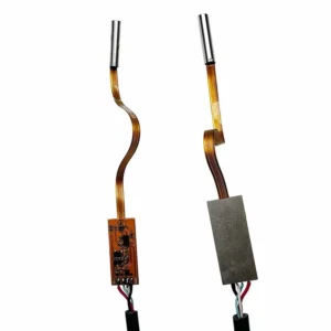
Modern healthcare relies heavily on visual diagnostics. Whether a clinician is examining the nasal cavity, inspecting the ear canal, evaluating soft tissue, or performing a detailed dental assessment, image quality plays a critical role in diagnosis and patient communication. Over the past decade, the demand for advanced medical endoscope camera systems and high-resolution intraoral camera dental solutions has increased significantly. Healthcare providers are no longer looking for basic imaging devices. They need compact, reliable cameras capable of delivering clear, real-time images while maintaining patient comfort. This shift has driven the development of smaller, more powerful imaging modules that can fit into extremely confined spaces without sacrificing image quality. Why Image Quality Matters in Medical Imaging A medical examination often depends on subtle visual details. Small changes in tissue color, early signs of inflammation, tiny cracks in a tooth surface, or hidden areas within the oral cavity can all influence clinical decisions. If the imaging system cannot capture these details clearly, diagnosis becomes more challenging. This is why image resolution, lighting performance, viewing angle, and thermal management are important considerations when selecting a medical endoscope camera. For healthcare professionals, the goal is not simply to capture an image but to obtain a clear visual representation that supports accurate evaluation and treatment planning. The Growing Role of Intraoral Cameras in Dentistry Patient expectations have changed dramatically in modern dental practices. Patients increasingly want to see what dentists see. Instead of relying solely on verbal explanations, dentists now use intraoral camera dental systems to display real-time images of teeth, gums, restorations, and treatment areas directly on a monitor. This visual approach offers several advantages: Improved patient understanding Better treatment acceptance More accurate documentation Enhanced communication Easier monitoring of treatment progress A compact camera with good illumination and close-range focus allows dental professionals to capture detailed images that may be difficult to observe with the naked eye alone. What Makes a Good Medical Endoscope Camera? Not all imaging modules are designed for healthcare environments. Several characteristics are particularly important when selecting a medical endoscope camera: Compact Diameter A smaller camera diameter improves access to narrow anatomical pathways while helping maintain patient comfort during examinations. Stable Image Quality Consistent HD imaging allows clinicians to identify fine details without excessive distortion or image noise. Reliable Illumination Integrated LED lighting helps provide even illumination across examination areas, reducing shadows and improving visibility. Low Heat Generation Thermal control is essential for devices used near sensitive tissues. Excessive heat can affect comfort and limit operating time. Flexible Integration Options Different medical devices require different hardware layouts. Some applications benefit from an integrated design, while others require a separated architecture to maximize flexibility. A Compact Imaging Solution from Shenzhen Brilliant CMOS Technology To support modern medical and dental imaging requirements, Shenzhen Brilliant CMOS Technology developed its 3.9mm 720P imaging module based on the OmniVision OV9734 CMOS sensor. The ultra-slim camera head is designed for applications where space is limited but image quality remains critical. Key features include: 3.9mm compact diameter 720P HD resolution 30 FPS real-time video Multiple lens options Integrated LED illumination USB and Wi-Fi connectivity options Integrated and separated hardware configurations The compact design makes the module suitable for both medical endoscope camera systems and intraoral camera dental equipment where maneuverability and visibility are equally important. Applications in Medical and Dental Devices ENT Examination Systems The slim profile allows healthcare professionals to access narrow ear and nasal passages while maintaining a clear visual field throughout the examination. Dental Imaging Equipment When used as an intraoral camera dental solution, the module provides detailed visualization of teeth, restorations, gum tissue, and treatment areas. Diagnostic Imaging Devices The camera can be integrated into specialized diagnostic tools that require compact dimensions and consistent HD image quality. Inspection of Difficult-to-Reach Areas Its small diameter and customizable viewing angles allow clear observation of areas that may be difficult to access using larger imaging systems. Choosing the Right Optical Configuration Different clinical procedures require different viewing perspectives. For detailed close-range inspections, narrower field-of-view lenses can provide greater magnification and clarity. Wider lens options help capture larger treatment areas and improve navigation during examinations. Shenzhen Brilliant CMOS Technology offers multiple lens configurations ranging from 70° to 140°, allowing device manufacturers to select the most suitable optical profile for their intended application. Final Thoughts As healthcare continues to embrace digital imaging, the demand for reliable medical endoscope camera systems and advanced intraoral camera dental technology will continue to grow. Image clarity, patient comfort, device size, and thermal performance all contribute to the effectiveness of modern diagnostic equipment. By combining a compact 3.9mm design, HD imaging performance, flexible optical configurations, and multiple integration options, Shenzhen Brilliant CMOS Technology provides a practical imaging solution for developers creating next-generation medical and dental devices.

Read More »

We will contact you within 1 working day, please pay attention to the email with the suffix “@cbritech.com”

One Request, Multiple Quotes