
USB Camera Modules: The Complete OEM Buyer’s Guide for Industrial and Embedded Vision Systems
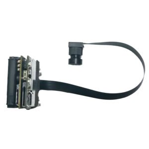
A camera module can look simple from the outside: a sensor, a lens, a circuit board and a cable. In a finished product, however, it becomes the visual input for an entire system. It may need to identify a face in uneven lighting, inspect a moving component, capture a document without distortion or deliver stable video inside a medical device. The quality of that visual input affects every decision the system makes afterward. For many original equipment manufacturers, a USB camera module provides the most practical route from imaging concept to working product. USB connectivity is familiar, widely supported and easier to integrate than many board-level interfaces. When the module follows the USB Video Class standard, a compatible host can often recognize it through an existing driver, reducing the amount of software development required during prototyping and deployment. That convenience does not make every USB camera interchangeable. Resolution, sensor architecture, shutter type, frame rate, lens, image signal processing, cable design, heat management and mechanical dimensions all influence whether a module will work reliably in the final device. This guide explains how engineers, sourcing teams and product managers can evaluate those factors before selecting an off-the-shelf module or requesting an OEM design. Contents What is a USB camera module? Why OEM teams choose USB for embedded vision How a USB camera module works USB 2.0 versus USB 3.0 Core specifications to evaluate Rolling shutter versus global shutter Common industrial and embedded applications How to build an OEM camera specification Prototyping, validation and mass production Frequently asked questions What Is a USB Camera Module? A USB camera module is a compact imaging assembly that sends video or still-image data to a host through a USB connection. A typical design combines a CMOS image sensor, lens, printed circuit board, image signal processor or bridge controller, memory, clock components, power regulation and a USB cable or connector. Depending on the design, the board may also support microphones, LEDs, infrared illumination, motorized focus or additional control inputs. The key difference between an OEM camera module and a consumer webcam is its intended method of integration. A webcam is a finished accessory. A module is a component that can be installed inside another product, adapted to a custom enclosure and tuned for a defined viewing distance, lighting condition and processing workflow. It can therefore be designed around the requirements of a kiosk, robot, scanner, laboratory instrument, access terminal or industrial inspection station. Many USB modules use UVC, or USB Video Class, which allows supported operating systems to communicate with the camera through a standard video-device framework. This can simplify development on Windows, Linux and Android platforms, although compatibility still needs to be tested on the exact host board, operating-system build and application stack used in production. Why OEM Teams Choose USB for Embedded Vision USB is attractive when a product requires a direct connection to a PC, industrial computer, single-board computer or embedded host with a usable USB port. Instead of routing a short-range sensor interface directly into a processor, the camera module handles part of the image pipeline and presents itself as a peripheral. This often shortens the path from evaluation sample to functional prototype. Faster integration: UVC-compatible modules can reduce driver work and allow early testing with common capture software or standard video APIs. Flexible placement: A cable allows the optical assembly to be positioned away from the host processor, which is useful in kiosks, robots and larger instruments. Broad host support: USB is available on many industrial PCs, mini PCs, edge computers and development boards. Useful resolution range: USB camera boards are available from compact VGA designs to high-resolution and high-frame-rate modules. Practical customization: Manufacturers can adjust the PCB shape, connector, cable, lens, focus range, firmware and image tuning without redesigning the entire host platform. USB is not automatically the correct interface for every product. Very small mobile devices, tightly integrated consumer electronics and designs that connect a sensor directly to a system-on-chip may be better served by MIPI camera modules. USB becomes especially compelling when development speed, host compatibility, cable reach and replaceable modular hardware matter more than achieving the smallest possible electronics footprint. How a USB Camera Module Works The imaging process begins when the lens directs light onto the sensor. The sensor converts light into electrical signals, which are read as pixel data. The signal then passes through processing stages that can include demosaicing, exposure control, white balance, noise reduction, sharpening, color correction and compression. A USB controller packages the resulting stream for transmission to the host. The host enumerates the camera when it is connected, identifies the supported video formats and exposes those options to the application. The application may then request a specific resolution, frame rate and pixel format. Actual performance depends on the complete data path: sensor output, internal processing, USB controller, cable, host port, CPU load, memory bandwidth and application design. The image sensor remains one of the most important components. CBRITECH groups board-level products within its CMOS sensor camera module range, where different sensor and interface combinations can be considered for compact embedded products. Sensor selection should be based on more than megapixels; pixel size, dynamic range, sensitivity, shutter architecture and availability may be more important to the final result. USB 2.0 Versus USB 3.0 Camera Modules The interface version determines the amount of transmission headroom available, but the name printed on the module does not tell the whole story. USB 2.0 is often sufficient for standard-resolution video, compressed formats and applications where cost and compatibility are more important than maximum throughput. USB 3.0 provides substantially more bandwidth and is usually preferred for higher resolution, higher frame rates, lower latency or less-compressed image data. Selection Factor USB 2.0 USB 3.0 Typical fit Standard HD video, compressed streams, cost-sensitive products High-resolution, high-frame-rate and lower-latency imaging Bandwidth headroom Limited for uncompressed high-resolution output Better suited to larger data streams Host availability Very broad Requires a suitable USB 3.x host path Cable and layout sensitivity Generally easier