
A camera module can look simple from the outside: a sensor, a lens, a circuit board and a cable. In a finished product, however, it becomes the visual input for an entire system. It may need to identify a face in uneven lighting, inspect a moving component, capture a document without distortion or deliver stable video inside a medical device. The quality of that visual input affects every decision the system makes afterward.
For many original equipment manufacturers, a USB camera module provides the most practical route from imaging concept to working product. USB connectivity is familiar, widely supported and easier to integrate than many board-level interfaces. When the module follows the USB Video Class standard, a compatible host can often recognize it through an existing driver, reducing the amount of software development required during prototyping and deployment.
That convenience does not make every USB camera interchangeable. Resolution, sensor architecture, shutter type, frame rate, lens, image signal processing, cable design, heat management and mechanical dimensions all influence whether a module will work reliably in the final device. This guide explains how engineers, sourcing teams and product managers can evaluate those factors before selecting an off-the-shelf module or requesting an OEM design.
Contents
- What is a USB camera module?
- Why OEM teams choose USB for embedded vision
- How a USB camera module works
- USB 2.0 versus USB 3.0
- Core specifications to evaluate
- Rolling shutter versus global shutter
- Common industrial and embedded applications
- How to build an OEM camera specification
- Prototyping, validation and mass production
- Frequently asked questions
What Is a USB Camera Module?
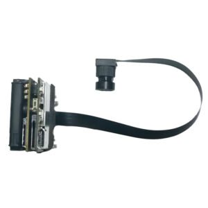
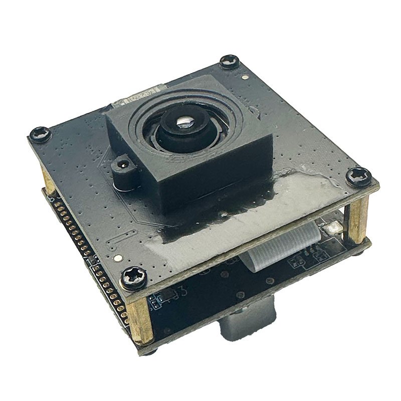
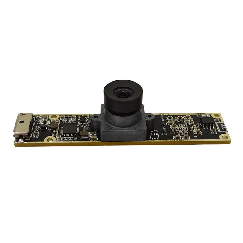
A USB camera module is a compact imaging assembly that sends video or still-image data to a host through a USB connection. A typical design combines a CMOS image sensor, lens, printed circuit board, image signal processor or bridge controller, memory, clock components, power regulation and a USB cable or connector. Depending on the design, the board may also support microphones, LEDs, infrared illumination, motorized focus or additional control inputs.
The key difference between an OEM camera module and a consumer webcam is its intended method of integration. A webcam is a finished accessory. A module is a component that can be installed inside another product, adapted to a custom enclosure and tuned for a defined viewing distance, lighting condition and processing workflow. It can therefore be designed around the requirements of a kiosk, robot, scanner, laboratory instrument, access terminal or industrial inspection station.
Many USB modules use UVC, or USB Video Class, which allows supported operating systems to communicate with the camera through a standard video-device framework. This can simplify development on Windows, Linux and Android platforms, although compatibility still needs to be tested on the exact host board, operating-system build and application stack used in production.
Why OEM Teams Choose USB for Embedded Vision
USB is attractive when a product requires a direct connection to a PC, industrial computer, single-board computer or embedded host with a usable USB port. Instead of routing a short-range sensor interface directly into a processor, the camera module handles part of the image pipeline and presents itself as a peripheral. This often shortens the path from evaluation sample to functional prototype.
- Faster integration: UVC-compatible modules can reduce driver work and allow early testing with common capture software or standard video APIs.
- Flexible placement: A cable allows the optical assembly to be positioned away from the host processor, which is useful in kiosks, robots and larger instruments.
- Broad host support: USB is available on many industrial PCs, mini PCs, edge computers and development boards.
- Useful resolution range: USB camera boards are available from compact VGA designs to high-resolution and high-frame-rate modules.
- Practical customization: Manufacturers can adjust the PCB shape, connector, cable, lens, focus range, firmware and image tuning without redesigning the entire host platform.
USB is not automatically the correct interface for every product. Very small mobile devices, tightly integrated consumer electronics and designs that connect a sensor directly to a system-on-chip may be better served by MIPI camera modules. USB becomes especially compelling when development speed, host compatibility, cable reach and replaceable modular hardware matter more than achieving the smallest possible electronics footprint.
How a USB Camera Module Works
The imaging process begins when the lens directs light onto the sensor. The sensor converts light into electrical signals, which are read as pixel data. The signal then passes through processing stages that can include demosaicing, exposure control, white balance, noise reduction, sharpening, color correction and compression. A USB controller packages the resulting stream for transmission to the host.
The host enumerates the camera when it is connected, identifies the supported video formats and exposes those options to the application. The application may then request a specific resolution, frame rate and pixel format. Actual performance depends on the complete data path: sensor output, internal processing, USB controller, cable, host port, CPU load, memory bandwidth and application design.
The image sensor remains one of the most important components. CBRITECH groups board-level products within its CMOS sensor camera module range, where different sensor and interface combinations can be considered for compact embedded products. Sensor selection should be based on more than megapixels; pixel size, dynamic range, sensitivity, shutter architecture and availability may be more important to the final result.
USB 2.0 Versus USB 3.0 Camera Modules
The interface version determines the amount of transmission headroom available, but the name printed on the module does not tell the whole story. USB 2.0 is often sufficient for standard-resolution video, compressed formats and applications where cost and compatibility are more important than maximum throughput. USB 3.0 provides substantially more bandwidth and is usually preferred for higher resolution, higher frame rates, lower latency or less-compressed image data.
| Selection Factor | USB 2.0 | USB 3.0 |
| Typical fit | Standard HD video, compressed streams, cost-sensitive products | High-resolution, high-frame-rate and lower-latency imaging |
| Bandwidth headroom | Limited for uncompressed high-resolution output | Better suited to larger data streams |
| Host availability | Very broad | Requires a suitable USB 3.x host path |
| Cable and layout sensitivity | Generally easier | Signal integrity and cable quality become more critical |
| Common applications | Kiosks, document capture, conferencing, access devices | Machine vision, motion analysis, advanced robotics, 4K imaging |
A USB 3.0 label does not guarantee a particular frame rate. A high-resolution sensor may still be limited by the sensor readout, bridge controller, firmware, pixel format or host software. Similarly, a carefully configured USB 2.0 module can perform well when MJPEG or another compressed format keeps the data rate within the available bandwidth. Engineers should evaluate the required output mode rather than choosing the interface by version number alone.
Projects that must freeze fast movement should also review the global shutter camera module collection. Interface bandwidth and shutter type solve different problems: bandwidth determines how efficiently data reaches the host, while shutter architecture affects how motion is captured at the sensor.
Core Specifications to Evaluate Before Buying
1. Resolution and Frame Rate
Resolution determines how much spatial detail the image can contain, while frame rate determines how frequently the scene is sampled. More pixels can help with OCR, facial detail, measurement and digital cropping, but they also increase data volume, processing load and storage requirements. A lower-resolution module with the correct optics and lighting can outperform a higher-resolution module that is poorly matched to the application.
Define the smallest feature that must be detected, the field of view, working distance and required processing speed. From there, calculate whether the target occupies enough pixels for the intended algorithm or human operator. For a moving production line, stable frame timing may matter more than maximum still-image resolution.
2. Sensor Size, Pixel Size and Low-Light Performance
Larger pixels generally collect more light, although final performance also depends on sensor generation, lens aperture, exposure time and image processing. Low-light applications should be tested with the actual illumination spectrum and exposure limits. Extending exposure may brighten the image but can introduce motion blur. Increasing gain can reveal detail but also increases noise.
3. Lens and Field of View
The lens determines what the sensor sees. Wide-angle lenses capture more of the scene but can introduce distortion and reduce the number of pixels assigned to a small target. Narrower lenses provide more detail at distance but require more accurate positioning. Buyers should specify horizontal, vertical or diagonal field of view rather than using the word wide-angle without a measurement.
Working distance also affects focus strategy. A fixed-focus camera can be stable and economical when the subject remains within a known range. Autofocus is useful when subject distance changes, but it introduces control behavior, focusing time and additional validation requirements. Some inspection applications require manual-focus or locked-focus assemblies to prevent the optical setting from drifting after calibration.
4. Pixel Format and Compression
Common USB camera output formats include YUY2 or YUYV and MJPEG. Uncompressed or lightly processed formats preserve predictable image data but require more bandwidth. MJPEG reduces the transmitted data volume and can make higher resolutions practical over USB 2.0, but the host must decode the stream and compression may affect fine detail. The correct choice depends on whether the application values visual quality, deterministic analysis, low latency or reduced host bandwidth.
5. Dynamic Range, WDR and HDR Behavior
Scenes containing bright windows, headlights, reflective metal or deep shadow can exceed a sensor’s usable dynamic range. In these environments, ordinary exposure control may preserve one area while losing detail in another. A wide dynamic range design can improve visibility across the scene, although WDR modes may affect frame rate, motion rendering or noise.
For access systems, video doorbells, face recognition and other high-contrast environments, evaluate purpose-built WDR camera modules using the actual backlighting conditions expected in the product.
6. Color, Monochrome and Infrared Requirements
Color imaging is useful when hue carries meaningful information, but monochrome sensors can be advantageous when sensitivity, contrast or measurement consistency matters more than color. Removing the color filter array allows a monochrome design to use more of the available light for luminance information. This can benefit scanning, machine vision and low-light systems.
Buyers developing inspection or scientific systems can compare dedicated monochrome camera modules. Day-and-night systems should also consider the spectral response of the sensor, IR-cut filter behavior and infrared illumination rather than assuming a normal color module will perform well in darkness.
Rolling Shutter Versus Global Shutter
A rolling shutter exposes or reads different rows of the sensor at slightly different times. It is common, cost-effective and suitable for many stationary or moderate-motion scenes. When the camera or subject moves quickly, the time difference between rows can bend straight lines, skew rotating objects or distort position measurements.
A global shutter captures the active image area at the same exposure moment, making it better suited to fast motion, barcode capture, robotic guidance and dimensional inspection. It may carry trade-offs in cost, resolution, sensitivity or sensor availability, so it should be selected because the application needs motion accuracy, not because it sounds more advanced.
| Requirement | Rolling Shutter | Global Shutter |
| Stationary subjects | Usually suitable | Suitable |
| Fast conveyor or rotating parts | Risk of geometric distortion | Preferred |
| Cost-sensitive high-resolution imaging | Often advantageous | May involve trade-offs |
| Measurement of moving targets | Use only after motion testing | Generally better suited |
Common Applications for USB Camera Modules
Industrial Inspection and Machine Vision
A USB camera can inspect labels, connectors, solder joints, packaging, surface defects and assembly presence. The most important variables are often repeatable lighting, optical geometry, trigger timing and motion control. A high megapixel count cannot compensate for glare, vibration or an unstable working distance. For moving production lines, high frame rate and global shutter operation may be central to reliable detection.
Robotics and Autonomous Equipment
Robots use cameras for navigation, object recognition, teleoperation, pick-and-place and human-machine interaction. USB makes it practical to connect the optical module to an edge computer without placing the processor directly behind the sensor. The design must still account for vibration, cable flexing, latency, synchronization and changing illumination.
Document Capture, OCR and Smart Kiosks
Document scanners and service terminals need consistent focus, low distortion, even illumination and enough resolution to preserve small text. Autofocus may help when users present objects at varying distances, while a fixed geometry may benefit from a calibrated fixed-focus lens. OCR accuracy should be tested on real documents, including reflective cards, folded paper and different print qualities.
Biometrics, Access Control and Face Recognition
Face-based systems must handle changes in user height, distance, pose and background lighting. WDR, exposure tuning, anti-flicker settings and lens field of view should be evaluated together. Image quality must be judged by recognition performance, not only by whether the video looks attractive on a monitor.
Medical and Laboratory Equipment
Medical and laboratory products may require compact dimensions, accurate color, cleanability, low heat and long product availability. The camera supplier should understand that integration into a medical device may involve risk management, documentation and validation obligations beyond the camera component itself.
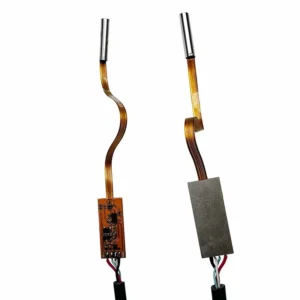
Where the optical assembly must enter a narrow cavity or inspection channel, a conventional USB board may be paired with or replaced by a specialized endoscope camera module. Diameter, illumination, sealing, cable construction and distal-tip heat then become major design constraints.
Agricultural, Outdoor and Thermal Systems
Outdoor and agricultural imaging introduces sunlight variation, moisture, dust, temperature swings and long working distances. A waterproof housing does not automatically make the electronics suitable for every environment; sealing method, lens window, condensation control, connector choice and operating-temperature validation all matter.
Visible-light USB cameras can support crop monitoring, equipment guidance and inspection, while systems that need heat-pattern detection should evaluate a dedicated thermal camera module core. Thermal and visible imaging solve different problems and should not be treated as interchangeable technologies.
How to Build an OEM USB Camera Specification
A useful request for quotation should describe the application before listing components. Suppliers can recommend a better architecture when they understand what the camera must see, where it will operate and how the host will process the stream. The following specification framework helps reduce avoidable sample cycles.
- Application and target: What object, feature, person or area must the camera capture?
- Working distance: Minimum, typical and maximum distance from lens to subject.
- Field of view: Required scene width and height at the working distance.
- Image output: Resolution, frame rate, pixel format and compression requirements.
- Motion: Camera speed, subject speed and whether distortion is acceptable.
- Lighting: Indoor, outdoor, infrared, backlit, flickering or controlled illumination.
- Focus: Fixed, manual or autofocus, plus required focusing range.
- Host platform: Processor, operating system, USB port type and application framework.
- Mechanical envelope: Maximum PCB size, mounting holes, connector direction and cable routing.
- Environment: Operating temperature, vibration, dust, moisture and cleaning requirements.
- Commercial needs: Prototype quantity, annual volume, lifecycle and target schedule.
OEM and ODM Customization Options
A standard sample is valuable for confirming sensor performance and software compatibility, but production hardware often needs refinement. A camera-module supplier may customize the PCB outline, mounting-hole positions, USB connector, cable length, cable exit direction, lens mount, field of view, focus distance, housing, LED arrangement, microphone, firmware descriptors and image-processing parameters.
Image tuning deserves particular attention. Automatic exposure, white balance, gain, sharpness, saturation, gamma, denoising and anti-flicker behavior influence real-world performance. Settings that look good in a bright office may fail in a dim warehouse or under LED lighting. Tuning should therefore be performed against defined scenes and acceptance criteria.
Customization also needs lifecycle planning. Engineers should ask how long the sensor and bridge controller are expected to remain available, whether substitute components can be qualified and how firmware revisions will be controlled. A camera integrated into a long-life industrial product should not depend on an undocumented consumer supply chain.
Prototyping, Validation and Mass Production
The first sample should answer architectural questions, not serve as automatic approval for mass production. Begin by confirming host recognition, supported video modes, stability and image quality. Then test the module inside the intended enclosure because lens windows, reflections, mounting stress and thermal conditions can change performance.
- Enumeration and recovery after repeated connection, sleep, restart and power interruption.
- Frame rate, dropped-frame behavior and latency under realistic host CPU load.
- Image quality across minimum and maximum lighting conditions.
- Focus consistency, lens retention and vibration resistance.
- Cable performance at the required length and bend radius.
- Temperature rise inside the enclosure during continuous operation.
- Compatibility with the production operating-system image and application version.
- Unit-to-unit consistency across a pilot batch rather than a single engineering sample.
Before production approval, agree on golden samples, inspection criteria, firmware identification and change-notification procedures. These controls are especially important when the camera feeds an algorithm: a visual change that appears minor to a person can shift model accuracy or measurement results.
Common Selection Mistakes to Avoid
- Choosing by megapixels alone: Resolution must be considered with optics, target size, frame rate, lighting and host bandwidth.
- Ignoring the output format: A quoted resolution may be available only in a compressed format or at a lower frame rate than expected.
- Testing only on a desktop PC: The final embedded host may have different drivers, power behavior and USB performance.
- Using a rolling shutter for fast motion without validation: Motion distortion can undermine inspection and tracking accuracy.
- Leaving lens requirements until the end: Field of view and focus determine whether the target is usable in the captured image.
- Approving one sample without pilot testing: Production consistency, cable quality and tuning variation should be checked across multiple units.
- Forgetting product lifecycle: A technically suitable module can still create risk if key components cannot support the product’s planned lifetime.
Why Work With CBRITECH for an OEM USB Camera Project?
CBRITECH supplies camera modules across USB, CMOS, feature-specific, endoscope and thermal imaging categories. This broader portfolio is useful when a project must compare more than one imaging architecture or requires a module adapted to a specific resolution, shutter, lens, form factor or application.
A productive supplier discussion should go beyond asking for a catalog number. Share the host platform, mechanical drawing, target scene, viewing distance, lighting, output requirements and expected production volume. With those inputs, the engineering team can help narrow the sensor, interface, lens and module structure before unnecessary prototype rounds accumulate.
Start by reviewing the available USB camera modules and identifying the closest reference design. For projects requiring a different embedded interface, compare the MIPI camera module range before finalizing the system architecture.
Frequently Asked Questions
What is the difference between a USB camera module and a webcam?
A webcam is normally a finished consumer peripheral with an enclosure and fixed feature set. A USB camera module is a board-level component intended for integration into another product and can often be customized for lens, PCB, cable, firmware and image tuning.
Does every USB camera module work without a driver?
No. UVC-compatible cameras can often use an operating system’s standard video driver, but the exact host, operating-system version, video mode and application still require compatibility testing.
Should I choose USB 2.0 or USB 3.0?
Choose according to the required resolution, frame rate, pixel format, latency and host capability. USB 2.0 can be suitable for many compressed HD streams. USB 3.0 is generally better when the project needs more bandwidth, high frame rates or less-compressed output.
Is a global shutter always better than a rolling shutter?
No. Global shutter is valuable for fast motion and measurement, while rolling shutter sensors may offer advantages in cost, resolution or low-light performance. The correct choice depends on scene motion and accuracy requirements.
Can a USB camera module be customized for a small enclosure?
Yes. Possible changes can include PCB dimensions, mounting holes, connector orientation, cable routing, lens mount and housing. Mechanical feasibility depends on the selected sensor, controller and production volume.
What information should I send to a camera-module supplier?
Provide the application, working distance, field of view, resolution, frame rate, lighting, focus range, host platform, mechanical limits, operating environment, prototype quantity and expected annual volume.
Can USB camera modules be used for AI and computer vision?
Yes. The camera provides the image stream, while AI inference normally runs on the host or edge processor. Reliable AI performance depends on consistent optics, lighting, exposure and image tuning as well as the model itself.
Choose the Camera Around the System, Not the Specification Sheet
The best USB camera module is not simply the one with the highest resolution or newest interface. It is the module that delivers repeatable, usable images within the mechanical, electrical, software, environmental and commercial constraints of the finished product. A carefully defined requirement can save weeks of testing and prevent late-stage redesigns.
To discuss a new industrial, robotics, medical, kiosk or embedded vision project, contact the CBRITECH team with your target application and technical requirements. The team can help evaluate an existing USB camera module or plan an OEM/ODM configuration for your product.